Electrical
adjustments.
Adjustments are required after
replacing circuit components and certain mechanical parts.
It is important to
perform these adjustments only after all repairs and replacements have been
completed. Also, do not attempt these
adjustments unless you do not have proper equipment is available.
To do the adjustments, you need a
service remote control. There is no service remote control, to buy anywhere. Service remote
control can be prepared from the supplied user remote control.
See how to prepare a service
remote control, from the user remote control.
How
to make the service remote control unit.
Cut the marked portion shown below illustration, of your user remote control. There is a service button underneath. You can get access to Service Button.
Pressing it, can see the service mode screen.
Be carefull to do adjustments in service mode.
Service
mode:
1. Use the service remote control unit.
2. Turn the power on.
3. Press the service button on the service remote control unit as shown in fig.
Purity
check mode. Up
This mode cycles through full-screen displays of red, green, blue, and white to
check for non-active pixels.
1. Enter the service mode.
2. Each time pressing [7] button on the service remote control unit, the
display changes as follows.
Auto
calibration [component]
Purpose: to bring the color adjustment of each component into standard
alignment.
Symptom of maladjustment: if this adjustment is incorrect, component signals do
not reproduce the corresponding color.
1. Input 1080i 100% color bar signal.
2. Enter the service mode.
3. To enter the auto calibration adjustment mode, press [6] button on service
the remote control unit.
4. To start auto adjustment, press [1] button on the service remote control
unit.
- In the auto adjustment mode, “please wait” appears on the screen.
- Upon completion, “ok” appears on the screen.
Auto
calibration [DTV]
purpose: to bring the color adjustment of DTV into standard alignment.
Symptom of maladjustment: if this adjustment is incorrect, DTV signals do not
reproduce the corresponding color.
1. Enter the service mode.
2. To enter the auto calibration adjustment mode, press [6] button on the
service remote control unit.
3. To start auto adjustment, press [2] button on the service remote control
unit.
- In the auto adjustment mode, “please wait” appears on the screen.
- Upon completion, “ok” appears on the screen.
Auto
calibration [PC]
purpose: to bring the color adjustment of pc into standard alignment.
Symptom of maladjustment: if this adjustment is incorrect, pc signals do not
reproduce the corresponding color.
1. Input XGA 100% white signal.
2. Enter the service mode.
3. To enter the auto calibration adjustment mode, press [6] button on service
the remote control unit.
4. To start auto adjustment, press [3] button on the service remote control
unit.
- In the auto adjustment mode, “please wait” appears on the screen.
- Upon completion, “ok” appears on the screen.
The
following adjustment normally is not attempted in the field. Only when
replacing the LCD panel then adjust as a preparation.
White
balance adjustment [video]
purpose: to mix red, green and blue beams correctly for pure white.
Symptom of maladjustment: white becomes bluish or reddish.
1. Operate the unit for more than 20
minutes.
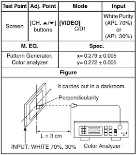
2. Input the white purity
3. Set the color analyzer to the
chroma mode and bring the optical receptor to the center on the lcd-panel
surface after zero point calibration as shown below.
Note: the optical receptor must be set perpendicularly to the LCD panel
surface.
4. Enter the service mode. press
[vol. dn] button on the service remote control unit and select “c/d1” mode.
3. Set the color analyzer to the
chroma mode and bring the optical receptor to the center on the lcd-panel
surface after zero point calibration as shown above.
Note: the optical receptor must be set perpendicularly to the LCD Panel surface.
4. Enter the service mode. Press [vol.dn] button on the service remote control
unit and select “c/d2” mode.
5. [Cutoff]
press [1] button to select “cor” for red cutoff adjustment. Press [3] button to
select “cob” for blue cutoff adjustment.
[Drive]
press [4] button to select “dr” for red drive adjustment. Press [6] button to
select “db” for blue drive adjustment.
6. In each color mode, press [ch.up/dn] buttons to adjust the values of color.
7. Adjust cutoff and drive so that the color temperature becomes 11000k (x=
0.279 / y= 0.272 ±0.005)
White
balance adjustment [component / DTV]
purpose: to mix red, green and blue beams correctly for pure white.
Symptom of maladjustment: white becomes bluish or reddish.
1. Operate the unit for more than 20
minutes.
2. Input the white purity. as
described above.
3. Set the color analyzer to the
chroma mode and bring the optical receptor to the center on the lcd-panel
surface after zero point calibration as shown below.
Note: the optical receptor must be set perpendicularly to the lcd panel
surface.
4. Enter the service mode. press [vol.dn] button on the service remote control
unit and select “c/d2” mode.
5. [cutoff]
press [1] button to select “cor” for red cutoff adjustment. Press [3] button to
select “cob” for blue cutoff adjustment.
[drive]
press [4] button to select “dr” for red drive.
press [6] button to select “db” for blue drive adjustment.
6. in each color mode, press [ch.up/dn] buttons to adjust the values of color.
7. Adjust cutoff and drive so that the color temperature becomes 11000k (x=
0.279 / y= 0.272 ±0.005).
How
to initialize the lcd television
1. turn the power on.
2. To enter the service mode, press the service button on the service remote
control unit.
To cancel the
service mode, press [power] button on the service remote control unit.
3. Press [display] button on the service remote control unit to initialize the
lcd television.
4. "ff" will appear in the upper left of the screen. "ff"
color will change to red from white when initializing is complete.
Test equipment
required
1. DC voltmeter
2. NTSC pattern generator (color bar w/white window, red color, dot pattern,
gray scale, monoscope, multi-burst)
3. Remote control unit
4. Color analyzer.
Schematic
[full]