Wednesday, December 14, 2016

Sony KLV-37M400A – LED LCD TV SMPS schematic

Used ICs: L6562DTR, DAS01A, DLA001DTR
PCB Top and foil side

Monday, December 12, 2016

Philco PH29E52DG 29 Inch LED LCD TV – SMPS, Backlight, power and LVDS circuit diagram

Used ICs: TEA1733, MT29F1G08ABA, BH3544, AMP5707, MP1495, MP1470, SY8066, 4953, AP9435
Headphone amplifier and Mute circuit
NAND Flash
Audio amplifier circuit
Power
LVDS
SMPS
Back-light inverter
Click on the schematics to zoom in

Saturday, December 10, 2016

Rotel RSX 1056, Rotel RSX 1057 Power and amplifier circuit diagram

Rotel SURROUND SOUND RECEIVER RSX-1057
Continuous Amplifier Power (five channels driven)
75 watts/ch (20-20k Hz, <0.05% THD, 8 ohms)
Continuous Amplifier Power (two channels driven)
100 watts/ch (1kHz, <1.0% THD, 8 ohms, DIN)
Power Requirements (AC)
120 volts, 60Hz (USA version)
230 volts, 50Hz (CE version)
Rotel SURROUND SOUND RECEIVER  RSX-1056
Continuous Amplifier Power (five channels driven)
75 watts/ch (20-20k Hz, <0.05% THD, 8 ohms)
Continuous Amplifier Power (two channels driven)
100 watts/ch (1kHz, <1.0% THD, 8 ohms, DIN)
Power Requirements (AC)
115 volts, 60Hz (USA version)
230 volts, 50Hz (CE version)
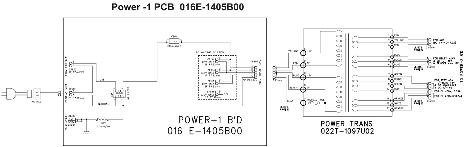
RSX1056 power schematic
RSX1056 Power amplifier schematic and PWB
RSX1057 Power schematic
RSX1057 Power amplifer schematic and PWB

Thursday, December 1, 2016

Philco Britania PB329BT – Circuit diagram and exploded view

Used ICs: M5673D, 1M*16SDRAM, CD5888, PT2314, TDA2822, RDA5807M, F-3088(BT-Module)
Circuit diagram (Click on the schematics to zoom in)
Exploded view

Tuesday, November 29, 2016

LE32H86 Haier LCD TV – SMPS, Audio output and T’Con schematic

Haier 32 inch LCD TV - LE32H86 - Power supply regulator and T'Con, and Audio output board circuit diagram.  Used ICs: MSH9010, SSC9502S, STR-A6059HMST6M181S 
Service mode Menu > 8 > 8 > 9 > 3 > Enter.
SMPS schematic
T'Con board
Audio output
Click on the schematics to magnify

Sunday, November 27, 2016

Philco PH32M LED LCD TV Power supply and audio output section schematic

Used ICs: JRC4558, TDA7266SA, NCP1606B, LD7531, 5A500V[FET], SG3525, LM358, 
Audio output
SMPS [Click on the schematics to zoom]

Thursday, November 24, 2016

CL21N11MJZXXAX Samsung DIGITAL TELEVISION RECEIVER Circuit diagram - Chassis : KS9A(N)

Used ICs: TDA9352PS/N21/3-OTP, 24C04, LA6510, 346VF2(Infrared sensor), KA5Q0765R | KA5Q0740RT(120v) | KA5Q0765RT (220V), KA7632, FCA173B(FBT), NJM2235D, AN7522N, MSP3425G-B7 and TDA6107Q [NTSC system – North America, South Central America and Mexico]
FOCUS Adjustment
1. Input a black and white signal.
2. Adjust the tuning control for the clearest picture.
3. Adjust the FOCUS control for well defined scanning lines in the center area of the screen.
Factory Adjustment
To enter the “Service Mode”, Press the remote-control keys in this sequence :
- If you do not have Factory remote-control
Picture OFF > Mute > 1 > 8 > 2 > Picture ON
- If you have Factory remote-control
Picture ON > Display > Factory
Circuit diagram
Click on the circuit diagrams to magnify

Wednesday, November 23, 2016

Sony HCD ZUX9 circuit diagram - MINI Hi-Fi COMPONENT SYSTEM - US Model, E Model, Australian Model

ICs Used: STK412-150C – IS81LV6416-10TLT[S-RAM] – TMP92CD28AFG[USB controller] – M30624MGP-B33FPU0(US) or M30624MGP-B34FPU0(Except US)[System control] – M61537FP-RF0G(Rec-Playback AMP) – BH2210FV-E2 
Click on the pictures to zoom in
AUDIO POWER SPECIFICATION
(US model only)
POWER OUTPUT AND TOTAL HARMONIC DISTORTION:
With 6-ohm loads, both channels driven, from 120 Hz – 10 kHz; rates 160 watts per channel minimum RMS power, with no more than 10 % total harmonic distortion from 250 milliwatts to rated output.
Amplifier section
The following are measured at US model:
AC 120 V, 60 Hz
Other models:
AC 120, 220, 240 V, 50/60 Hz
Front/Surround speaker Power Output (rated): 160 W + 160 W (at 6 Ω, 1 kHz, 1% THD)
RMS output power (reference): 250 W + 250 W (per channel at 6 Ω, 1 kHz, 10% THD)
USB board schematic
Transformer board schematic
Main board schematic
Power amplifier board schematic

Friday, October 28, 2016

Sanyo C29LF41 - CRT TV circuit diagram

Sanyo C21LF41, Sanyo C21LF41B. 
PhilcoPF2127, PF2107, PS2117. 
NisatoTVZ2001M. 
Stell Home SHT212F.
Diplomatic GMTV114M, GMTV210M, GMTV12. 
Noblex 14TC669,20TC670, 21TC671F, 21TC672F, 21TC674.
Used ICs: QXXAVC570 = STR-W6753, SE130NH, LA78040N / B / E, LA42032E, CXA2234QP,QXXAVC890 = LA76931ADE58S / E
SMPS split
Full circuit diagram