Used ICs - STR-G5643D
– NT6865UG – STV9118 – LM1246 – LM 1248 – M1237BDKE - LM2470TA – STV9302A – 79A774-1
[LOT] – 2SC5929 [HOT Transistor]


Maintain
interconnecting ground lead connections between chassis and picture tube dag
when operating chassis. Certain HV
failures can increase X-ray radiation. Monitor should not be operated with HV
levels exceeding the specified rating for the chassis type. The maximum
operating HV specified for the chassis used in this monitor is
24.8KV ± 1KV with a line voltage of 120/240 VAC. Higher voltage may also increase possibility of failure in HV supply.
It is important to maintain specified values of all components in the horizontal and high voltage circuits and anywhere else in the monitor that could cause a rise in high voltage or operating supply voltages. No changes should be made to the original design of the monitor. Components shown in the shaded areas on the schematic should be replaced with exact factory replacement parts. The use of unauthorized substitute parts may create a shock, fire or other hazard. To determine the presence of high voltage, use accurate, high impedance, HV meter connected between second anode lead and CRT dag grounding device. When servicing the High Voltage System, remove static charge from it by connecting a 10K ohm resistor in series with an insulated wire (such as a test probe) between picture tube dag and 2nd anode lead.(AC line cord disconnected from AC power outlet.)
The picture tube used in this monitor employs integral implosion protection. Replace with tube of the same type number for continue safety. Do not lift picture tube by the neck. Handle the picture tube only after discharging the high voltage completely.
Circuit Diagram [Schematic] SMPS, Deflection and Video amplifier - Split


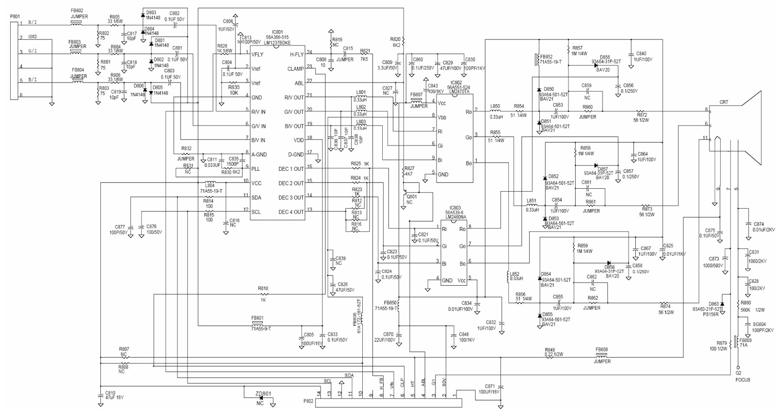
Full circuit

MICRO
Controller
The IC101 contains a 6502/8051 8-bit CPU core, 512 bytes of RAM, 16K bytes of ROM,14 channel 8 bit PWM D/A converters, 2 channel A/D converters for key detection, one 8 bit pre-loadable base timer, internal H-sync and V-sync signals processor providing mode detection, watch- dog timer preventing system from abnormal operation, and an I²C bus interface.
H/V sync signals processor
The functions of the sync processor include polarity detection, H-SYNC & V-SYNC signals counting, Programmable SYNC signals output, free running signal generator. Pin41/Pin42 are for the H-SYNC and VSYNC input, Pin33/Pin34 will output the same signal as input sync signal without delay, and the polarity are setting in the positive. When no signal input, the Pin33 will output a 72Hz V-SYNC free run signal. The Pin34 will output a 48KHz H-SYNC free run signal. for the monitor testing use.
Deflection
Circuit
The deflection circuit is achieved by a high performance and efficient solution IC401 (STV9118) for this monitor. The concept is fully DC controllable and can be used in applications with a micro-controller solutions. The STV9118 provides sync. Processing with full auto sync. Capability, a flexible SMPS block and an extensive set of geometry control facilities. Further the IC generates the drive waveforms for DC coupled vertical boosters to the TDA9302A.
Horizontal Oscillator
The oscillator is of the relaxation type and requires a capacitor of C409 at pin6. The free running frequency is determined by a resistor R412 from pin8 to ground.
PLL 1 Phase Detector
The phase detector is a standard one using switched current sources. It compares the middle of H-sync. With a fixed point on the oscillator saw-tooth voltage. The PLL loop filter C435, C437, R411 is connected to Pin9.
PLL2 Phase Detector
This phase detector is similar to the PLL1 detector and compares the line flyback pulse at pin 12 with the oscillator saw-tooth voltage. The PLL2 detector thus compensates for the delay in the external H-deflection circuit by adjusting the phase of the HDRV output pulses. The phase between H-flyback and H-sync can be controlled at pin5.
X-ray
Protection
The X-ray protection input pin25 provides a voltage detector with a precise threshold. If the voltage exceeds this threshold for a certain time, an internal latch switches the whole IC into protection mode. In this mode several pins are forced into defined states:
Pin28 (BDRV) is floating
Pin26 (HDRV) is floating
Vertical Oscillator
The vertical free – running frequency is determined by the capacitance C613 at pin22. Usually the free-running frequency should be lower than the minimum trigger frequency.