UX-S57 - CD-ROM No.SML200405

Block diagram

Printed circuit boards


Schematic diagrams


UX-S57 - CD-ROM No.SML200405
Samsung UE**B6000VWXXC, UE**B7000WWXXC, UE**B7020WWXXC-43 ,46 and 55 inch LCD TVs

Check List for Initial operation
Power cord in to the set
Power switch on
You can sound SMPS relay
* If you can’t sound, check the STB_5V appear at BD229 in main board Back-light
on
* If back-light not on, check the main board power line And check the dimming
cable Picture on or display the banner
* If display is nothing, check the LVDS cable And LVDS clk/data line
Inform to change the Assembly
Check the Side-Label Ver.
in set (important)
Order to the item with Side-Label Ver.
If you change the item, see the service-bulletin for setting the factory
option.
Inform about error messages
If set is connected
internet and software is old version, popup below message.
“
version XXXXX is available, upgrade?”
And select OK, you can update your LCD TV.
Panel or Main?

No Power

No video analogue PC

No video HDMI

No video Tuner-CVBS

No video Tuner DTV

No video CVBS

No video Component

No sound

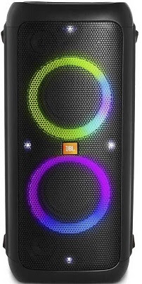
Applicable to:
JBLPARTYBOX200AS,
JBLPARTYBOX200BR, JBLPARTYBOX200CN, JBLPARTYBOX200EU, JBLPARTYBOX200IN,
JBLPARTYBOX200JN, JBLPARTYBOX200RU, JBLPARTYBOX200AM
JBLPARTYBOX300AS, JBLPARTYBOX300BR, JBLPARTYBOX300CN, JBLPARTYBOX300EU,
JBLPARTYBOX300IN,
JBLPARTYBOX300JN, JBLPARTYBOX300RU, JBLPARTYBOX300AM
SPECIFICATIONS
AC power input: 100-240V ~ 50/60Hz
DC power input: 12V 8A
Built-in battery: Li-ion 10.4Ah, 7.2V (PartyBox 300)
Power consumption: 60W
Standby power consumption: <2W with BT connecting;<0.5W without BT connecting
USB output: 5V 2.1A
Speaker drivers: 2 woofer + 3 tweeter
Speaker impedance: 4 ohm
Total output power: 120 W RMS
BLOCK DIAGRAM

G1-Block diagram

DC-DC CIRCUIT

BOOST CIRCUIT

MAIN BOARD CHARGE
CIRCUIT-BQ24610

MAIN BOARD MIC CIRCUIT

AUDIO IN CIRCUIT

ADC5536 CIRCUIT

MAIN CHIP
CIRCUIT-SPHE8107

MCU CIRCUIT

BT MODULE CIRCUIT

DSP CIRCUIT

CIRCUIT DIAGRAM-MAIN
BOARD

AMP CIRCUIT

CIRCUIT DIAGRAM-TOP
RGB LAMP RING BOARD

CIRCUIT DIAGRAM-BOTTOM
RGB LAMP RING BOARD

HCD-SH2000
is the tuner, USB, CD and amplifier section in FST-SH2000/LBT-SH2000
NOTE OF REPLACING THE IC102 AND IC4605 ON THE DMB21 BOARD
IC102 and IC4605 on
the DMB21 board cannot exchange with single. When these parts on the DMB21
board are damaged, exchange the entire mounted board.
NOTE OF REPLACEMENT OF THE MS-214
BOARD
When the MS-214
board is defective, exchange the entire MD (AU) ASSY.

MAIN BOARD DISCRIMINATION
In this set, the
MAIN board has been changed in the midway of production.
Repair after distinguishing each type
set to doing the repair referring to the following.
NOTE OF REPLACING THE IC103 AND C242 (Combination: TYPE B) ON THE MAIN
BOARD (Suffix-12)
IC103 and C242
(Combination: TYPE B) on the MAIN board (Suffix-12) cannot exchange with
single. When these parts on the MAIN board (Suffix-12) are damaged, remove
IC103 and C242 (Combination: TYPE B) and replace with IC102 and C239 (Combination:
TYPE A)

HOW TO EJECT THE DISC WHEN POWER SWITCH TURNS OFF or (No Power)
Note: Please take out the CD mechanism block from a set referring to
“SECTION 2 DISASSEMBLY”.

SIDE PANEL A, SIDE PANEL B AND TOP PANEL SECTION disassembly

TEST MODE
PANEL TEST MODE
This
mode is used to check the fluorescent indicator tube, LEDs, keys, [MASTER
VOLUME] jog, model, destination and software version.
Procedure:
1. Press [SEARCH] button and [OPTIONS] button simultaneously and hold 3
seconds.
2. All LEDs and segments in fluorescent indicator tube will light up.
3. When you want to enter to the software version display mode, press [FLANGER]
button. The model information appears on the fluorescent indicator tube. Press
[FLANGER] button again to view the destination information.
4. During the destination information display, press [FLANGER] button. Each
time [FLANGER] button is pressed, the fluorescent indicator tube shows the
version of each category software in the following sequence: SC, MTK (DMB Board
firmware version), UI, PF, SYS, CD, CDMA, CDMB, ST, TA, TAS, TM and return back
to model information display.
5. When [SEARCH] button is pressed while the version numbers are being
displayed except model and destination, the date of the software creation appears.
When [SEARCH] button is pressed again, the display returns to the software
version display.
6. Press [ISOLATOR] button, the key check mode is activated.
7. In the key check mode, the fluorescent indicator tube displays “K 0 V0”.
Each time a button is pressed, “K” value increases.
However, once a button has been pressed, it is no longer taken into account.
“V” value increases in the manner of 0, 1, 2, 3 ... if [MASTER VOLUME] knob is
turned clockwise, or it decreases in the manner of 0, 9, 8, 7 ... if [MASTER
VOLUME] knob is turned counter clockwise.
8. When [SOUND FLASH] button is pressed after all LEDs and segments in
fluorescent indicator tube light up, alternate segments in fluorescent
indicator tube and LEDs would light up. If you press [SOUND FLASH] button
again, another half of alternate segments in fluorescent indicator tube and
LEDs would light up. Pressing [SOUND FLASH] button again would cause all
segments in fluorescent indicator tube and LEDs light OFF. Pressing [SOUND
FLASH] button again would cause all segments in fluorescent indicator tube and
all LEDs light up.
9. To release from this mode, press the [SEARCH] button and [OPTIONS] button in
the same manner as step 1, or disconnect the power cord.
COMMON TEST MODE
This
mode is used to check operations of the Amplifier section.
Procedure:
To enter Common Test Mode
1. Press [USB/USB SELECT] button and [PRESET EQ] button simultaneously and hold
for 3 seconds.
2. The upper segments of fluorescent indicator tube will blink.
The function is changed to TV and the volume is changed to VOLUME MIN.
Check
of Amplifier
1. Press [PRESET EQ] button repeatedly until a message “GEQ MAX” appears on the
fluorescent indicator tube. GEQ increases to its maximum.
2. Press [PRESET EQ] button repeatedly until a message “GEQ MIN” appears on the
fluorescent indicator tube. GEQ decreases to its minimum.
3. Press [PRESET EQ] button repeatedly until a message “GEQ FLAT” appears on
the fluorescent indicator tube. GEQ is set to flat.
4. When the [MASTER
VOLUME] knob is turned clockwise even slightly, the sound volume increases to
its maximum and a message “VOLUME MAX” appears on the fluorescent indicator
tube.
5. When the [MASTER VOLUME] knob is turned counter clockwise even slightly, the
sound volume decreases to its minimum and a message “VOLUME MIN” appears on the
fluorescent indicator tube.
To release from Common Test mode
1. To release from this mode, press the POWER button.
2. The cold reset is enforced at the same time.
COLD RESET
The
cold reset clears all data including preset data stored in the EEPROM to
initial conditions. Execute this mode when returning the set to the customer.
Procedure:
1. Press the POWER button to turn on the system.
2. Press STOP button and POWER button simultaneously for 3 seconds.
3. “COLD RESET” appears on the fluorescent indicator tube.
After that, the fluorescent indicator tube becomes blank for a while, and the
system is reset.
TUNER STEP CHANGE
The
step interval of AM channels can be toggled between 9 kHz and 10 kHz. This mode
is not available for Saudi Arabian, European and Russian models.
Procedure:
1. Press POWER button to turn on the system.
2. Press [FUNCTION] button repeatedly to select the “AM”.
3. Press POWER button to turn off the system.
4. Press [ENTER] button and POWER button simultaneously. The system turns on
automatically. The message “AM 9K STEP” or “AM 10K STEP” appears on the
fluorescent indicator tube and thus the channel step is changed.
CD SHIP MODE (WITH MEMORY CLEAR)
This
mode moves the optical pick-up to the position durable to vibration and clears
all data including preset data stored in the data flash to initial conditions
during the next AC-In. Use this mode when returning the set to the customer
after repair.
Procedure:
1. Press POWER button to turn on the system.
2. Select CD function and without dics inserted.
3. Press [EJECT] button and POWER button simultaneously for 3 seconds. The
system turns off automatically.
4. A message “MECHA LOCK” is displayed on the fluorescent indicator tube and
the CD ship mode is set.
CD SHIP MODE (WITHOUT MEMORY CLEAR)
This
mode moves the optical pick-up to the position durable to vibration. Use this
mode when returning the set to the customer after repair.
Procedure:
5. Press POWER button to turn on the system.
6. Select CD function and without dics inserted.
7. Press [CD] button and POWER button simultaneously. The system turns off
automatically.
8. A message “MECHA LOCK” is displayed on the fluorescent indicator tube and
the CD ship mode is set.
DISC THEFT PREVENTION MODE
This mode let prevent disc to be ejected. When this
mode is activated, the disc will not eject when [EJECT] button is pressed.
The message “LOCKED” will be displayed on the fluorescent indicator tube. This
mode only applied when there is disc.
Procedure:
1. Press POWER button to turn on the system.
2. Select CD function.
3. Press [PLAY/PAUSE] button and [EJECT] button simultaneously for 3 seconds.
The message “LOCKED” or “UNLOCKED” displayed on the fluorescent indicator tube.
FACTORY PRESET
This mode is use to load all the factory use preset
frequencies into FM 1-FM 20 and AM 1-AM 10. Originally, frequency of FM 1-FM 20
and AM 1-AM10 are set to the minimum frequency.
Procedure:
1. Press POWER button to turn on the system.
2. Press [SEARCH] button and [TUNER/BAND] button simultaneously and hold for 3
seconds, message “FACTORY” appears on the fluorescent indicator tube. The
function is changed to TUNER automatically
FM AUTO STOP CHECK
Procedure:
1. Turn the power on.
2. Input the following signal from Signal Generator to FM antenna input
directly.
Carrier frequency : A = 87.5 MHz, B = 98 MHz, C = 108 MHz
|
Deviation |
: 75 kHz |
Note: Please
use 75 ohm “coaxial cable” to connect SG and the set. You cannot use video cable
for checking.
Please use SG whose output impedance is 75 ohm.
3. Set to FM tuner function and scan the input FM signal with automatic
scanning.
4. Confirm that input Frequency of A, B and C detected and automatic scanning
stops.
The stop of automatic scanning means “The station signal is received in good
condition”.
Display
board schematic

Volume
board schematic

NEXT MA3200 Hi-Power
Stereo power supply schematic


NEXT MA3200 Hi-Power
Stereo CH1 Power amplifier schematic

NEXT MA3200 Hi-Power
Stereo CH2 Power amplifier schematic

.jpg)

