DESIGN/SERVICE mode
To enter the USER SERVICE mode
Caution: The user service mode adjustment can be changed only when service personnel adjust the whole set data during servicing. As the control data have dramatic effects on functions and
performance of the TV, service personnel should not tell user how to enter the SERVICE mode to avoid improper data settings.
Set the volume to 0. Then press and hold the MUTE button on the remote control, and press the MENU button on the TV to enter the SERVICE mode. (In this case, the S mode cannot be stored in the EEPROM. To exit from the S mode, turn off the TV set.)
After entering the S mode, Red“ S”is displayed on the upper center of the screen and MENU1 is default. Use the POS+/- buttons to highlight an adjustment and the VOL+/- buttons to adjust
it. The adjusted data are immediately output and stored in the EEPROM.
EX-1A1 chassis series are applied in 21NF55/21PF93 respectively which uses mainly Philips’ advanced UOC-ultimate chip TDA935X/6X/8X and I2C-bus controlled IC. With combination of
microcontroller and small signal processor, the TDA935X/6X/8X series feature high-integration, high-performance-to-price ratio and high-reliability and advanced functions with fewer external
components, which provide much convenience for manufacturing and technical service.
The super chips TDA935X/6X/8X are good in pins compatibility. Differences among them are shown as follows.
TDA9351(48K) PAL/NTSC/SECAM+1 PAGE TELETEST
TDA9350(48K) PAL/NTSC+1 PAGE TELETEST
TDA9361(64K) PAL/NTSC/SECAM+10 PAGE TELETEST
TDA9360(64K) PAL/NTSC+10 PAGE TELETEST
TDA9380(32K) PAL/NTSC
TDA9387(32K) NTSC
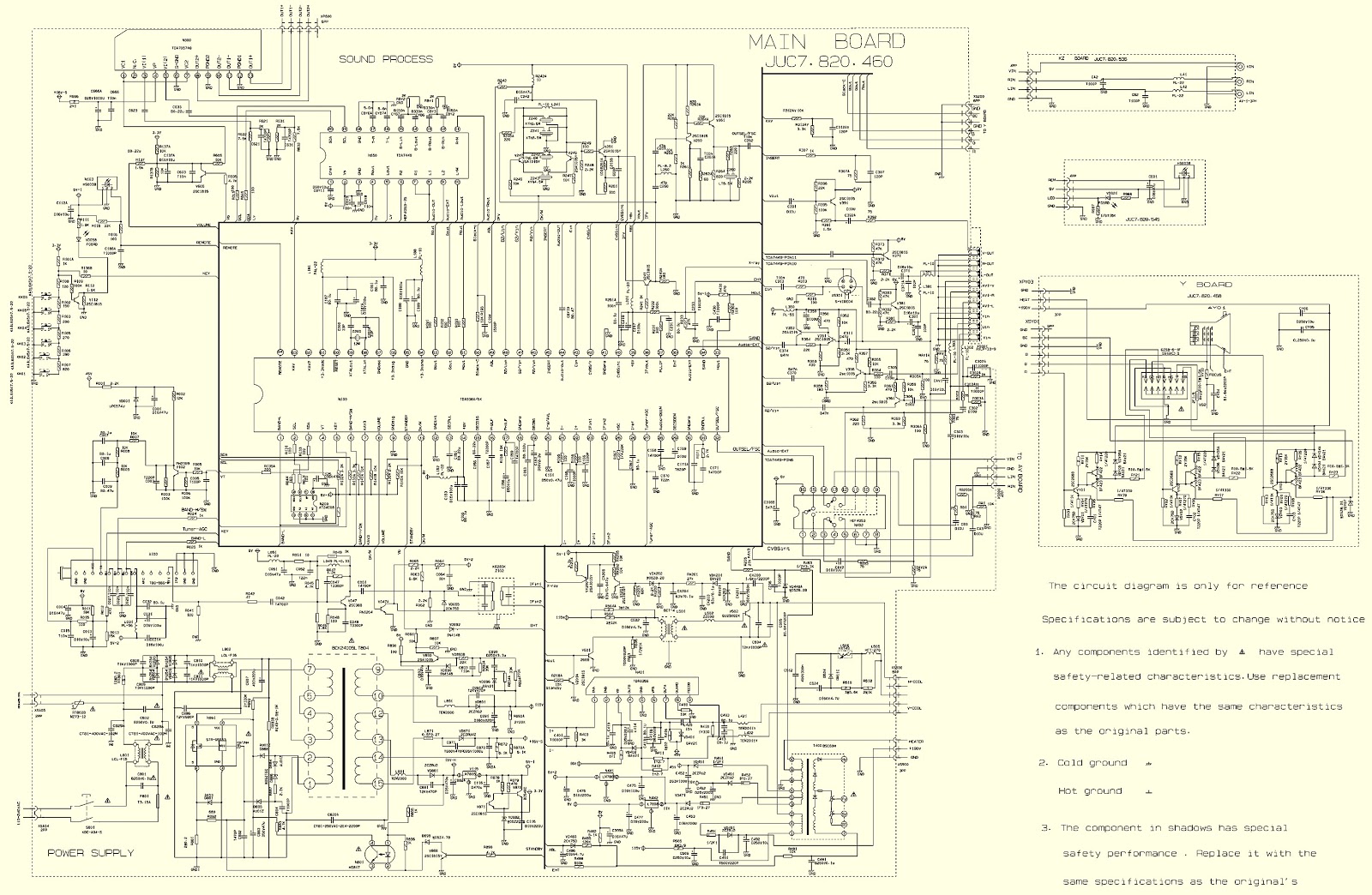
Circuit diagram & PWB
Click on the pictures to zoom in