Wednesday, September 28, 2016

LG 26H1DC1 – LCD TV – SMPS circuit diagram

26 inch LG LCD TV - LG26H1DC1 - power board circuit diagram
 SMPS Schematic LG 26H1DC1 – LCD TV
Click on the schematic to magnify

EXA37617801 SMPS– Used with LG42LC7R LCD TV - Schematic

Circuit diagram
Click on the schematic to zoom in

LG Mini Hi-Fi system – CM9740 – NS9740 – SMPS and Power Amplifier schematic

LG 2900W Combo Hi-Fi system CM9740 – Power and Amp: circuit diagram
SMPS schematic
Power amplifier schematic

Tuesday, September 27, 2016

Sansui SV2918 Circuit diagram

Used ICs: STR-F6656 – TCLM13 – TB1240 – 4052 – TA1216AN – TDA2616Q – TA8427K – TA1275A – TDA9181
SV2518 – 64CM
SV2916i – nicam/secam
SV2918 – nicam
SV3418 – 87 cm
PAL BG, I, DK, NTSC 4.43 – NTSC 3.58(AV)
Circuit diagram

Click on the schematics to zoom in

Monday, September 26, 2016

Changhong LT52510F - AOC L52BS83FU -SMPS SCHEMATIC. 715T2919-1. Components: IC901: UCC28019DR-IC902: STR-W6252-IC905: L6599D

Changhong and AOC LCD TV - power supply circuit diagram. 715T2929-1
Schematic
Click on the circuit diagrams to magnify

Sunday, September 25, 2016

Caixa Ativa Digital de 15 inch PV115d Schematic - IRFB31N208D

Peavey – PV1015D – PV115D – PV215D – PV2015D – Circuit diagram.  Used semiconductors: IRFB31N208D – IRS2092 – IR2153D [SMPS control] – IRFB460 [SMPS switching output] – NJM4580
SMPS Circuit diagram
Tone control and power amplifier circuit diagram
Click on the schematics to zoom in

Color TV circuit diagram using TDA9341 IC 14 and 21 inch – Service mode - Memory IC replacement

TDA9341 – AT24C08 - CD4052 – AN7522 – TDA2003 – [LOT 
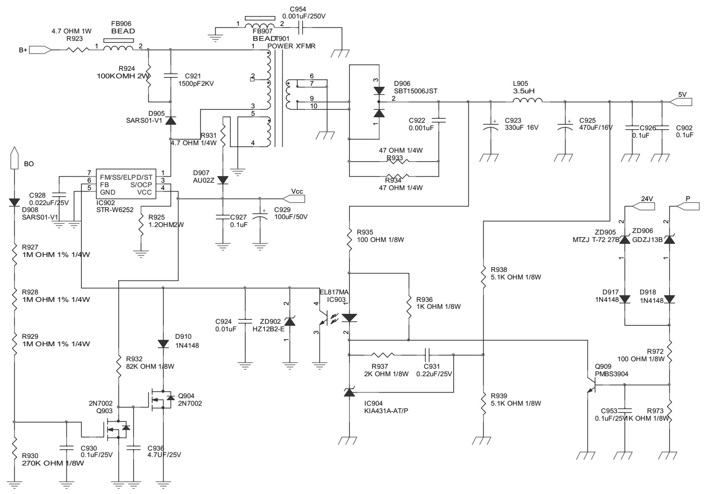
BSC25-N0832/BSC25-T1010A/BSC24-01N4014K] – Transistorized SMPS
FBT variations: FOR 29” 
BSC26-01-N4010F BSC26-N2143
BSC26-01N4010E BSC26-N2148
BSC26-01N4004F BSC26-01N
REPLACEMENT OF MEMORY IC
This TV circuit uses memory IC. In the memory IC are memorized data for correctly operating the video and deflection circuits.
When replacing memory IC, be sure to use IC written with the initial value of data.
PROCEDURE FOR REPLACING MEMORY IC
(1) Power off
Switch the power off and unplug the power cord from AC outlet.
(2) Replace IC
Be sure to use memory IC written with the initial data values.
(3) Power On
Plug the power cord into the AC outlet and switch the power On.
(4) Check and set system default value:
1) Press “MENU” key followed by digits '6''4''8' and '3'. Then Press “TEST” key on the Remote control unit for factory used.
2) The red “M”or”factory” will be displayed on the screen, repeat this and it will changed as follow: 
normal-M(factory)-BUS open-normal..
3) Press digital key, (Mkey) and corresponding on-screen display will be appeared.
4) Check the setting value of the SYSTEM default value of Table below. If the value is different, select items by [CH+]/[CH-] keys and set value by VOL+]/[VOL-] keys.
5) Press “STANDBY” key again and return to the normal screen.
Circuit diagram and PWB
BUS CONTROL ADJUSTMENT
TDA9351/9353: to enter BUS control mode, Press “MENU” key followed by digits '6''4''8' and '3'. Then press digit Press “0” to “9“ key, (Mkey) and corresponding on-screen display will be appeared.
TDA8370: to enter BUS control mode, Press “MENU” key followed by digits '6''4''8' and '3'. then Press “TEST” key on the Remote control unit twice for factory used(or press digits '6''4''8' and '3' twice.) and then press digit Press “0” to “9“ key, (Mkey) and corresponding on-screen display will be appeared.
On TV screen “TEST” will be indicated, this means entered bus control mode.
And press following key, each function will be available.

Samsung WS32Z108RT – SMPS and audio output schematic

Samsung 32 inch CRT TV - power and audio output circuit diagram
SMPS
Sub-power
Audio output
Click on the schematics to magnify

Saturday, September 24, 2016

Sony HCD-SHAKE33-SHAKE44-SHAKE55-SHAKE66-SHAKE77-SHAKE88 D-amp circuit diagram

• HCD-SHAKE33 is the tuner, USB, CD player, Bluetooth, NFC and amplifier section in SHAKE-33.
• HCD-SHAKE55 is the tuner, USB, CD player, Bluetooth, NFC and amplifier section in SHAKE-55.
• HCD-SHAKE77 is the tuner, USB, CD player, Bluetooth, NFC and amplifier section in SHAKE-77.
• HCD-SHAKE44 is the tuner, USB, CD/DVD player, Bluetooth, NFC and amplifier section in SHAKE-44D.
• HCD-SHAKE66 is the tuner, USB, CD/DVD player, Bluetooth, NFC and amplifier section in SHAKE-66D.
• HCD-SHAKE88 is the tuner, USB, CD/DVD player, Bluetooth, NFC and amplifier section in SHAKE-88D.
UK Model HCD-SHAKE33
Russian Model HCD-SHAKE66
E Model HCD-SHAKE33/SHAKE44/SHAKE55/SHAKE66/SHAKE77/SHAKE88
Argentina Model- Mexican Model HCD-SHAKE33/SHAKE55/SHAKE77
Australian Model HCD-SHAKE77
Malaysia ModelHCD-SHAKE44/SHAKE66/SHAKE88
Saudi Arabia Model South African Model Thai Model HCD-SHAKE44/SHAKE88
CD mechanism type – CD,90-DVBU202/M
Optical pickup – CMS-S76RFS7G
SHAKE-77/88D
WF (Woofers)/MID (Mid speakers)/TW (Tweeters)
Power Output (rated):
350 W + 350 W (at 4 ohms, 1 kHz, 1% THD)
RMS output power (reference): 600 W + 600 W (per channel at 4 ohms, 1 kHz)
SW (Subwoofers)
RMS output power (reference): 1,200 W + 1,200 W (per channel at 8 ohms, 100 Hz)
SHAKE-55/66D
WF (Woofers)/TW (Tweeters)
Power Output (rated):
350 W + 350 W (at 4 ohms, 1 kHz, 1% THD)
RMS output power (reference): 600 W + 600 W (per channel at 4 ohms, 1 kHz)
SW (Subwoofers)
RMS output power (reference): 900 W + 900 W (per channel at 10 ohms, 100 Hz)
SHAKE-33/44D
WOOFERS
Power Output (rated): 350 W + 350 W (at 4 ohms, 100 Hz, 1% THD)
RMS output power (reference): 600 W + 600 W (per channel at 4 ohms, 100 Hz) MID (Mid speakers)/TWEETERS
RMS output power (reference): 500 W + 500 W (per channel at 5 ohms, 1 kHz)
Main amplifier circuit diagram (Schematic)
Click on the schematics to magnify

Thursday, September 22, 2016

Akira 21WHS3-BN – 21 inch CRT TV – circuit diagram – UOC - TDA9381

Used ICs: 24C08 – NOM8370-B-16NB or TDA9381C38ND – AN7522N – STV9302A – KA5Q0765(STR)
SMPS [Split]

Wednesday, September 21, 2016

Sharp LC-32A28L– Sharp LC-42A48L – Service mode – adjustments – SMPS circuit diagram

How to enter service mode Sharp LC32A28L and Sharp LC42A48L LCD TVs – Alignment procedure – Power supply 715g 4009 and 715g 3905 - Schematic 
SERVICE MODE
To enter factory mode [Service mode] menu: press MENU + Numeric keys “1999” to enter factory mode.
To Exit, Power OFF.
Alignment method
Initial Set-up
1. Select source as “INPUT 2 ” (Component 1).
2. Set Smart Picture mode as “Standard”.
3. Apply “RGB Full white” pattern by signal generator or internal full white pattern.
4. Enter factory mode menu: press MENU + Numeric keys “1999”.
Alignment
1. At FAC mode menu, select ”19. Color temp” item and change to “Cool”
2. Apply RGB Full white pattern and change signal level to 204 (80% white pattern).

(2) If use internal pattern, set level to 818 (80% white pattern).
3. Adjust the 20. Scaler R GAIN, 22. Scaler B GAIN values to meet “Cool” color coordinates specification below. (Please keep 21. Scaler G GAIN at 0).
4. Apply RGB Full white pattern and change signal level to 48 (20% white pattern)
(4) If use internal pattern, set level to 204 (20% white pattern).
5. Adjust the 23. Scaler R Offset, 25.Scaler B Offset values to meet “Cool” color coordinates specification below. (Please keep 24.Scaler G Offset at 0)
6. Repeat step 2, 3, 4, 5, twice to meet “Cool” color coordinates specification below.
7. Select ”26. Clr temp Copy” item and perss RC “ X”. The Cool adjust value will copy to all of input source automatically.
8. Select ”19. Color temp” item and change to “Normal”.
9. Apply RGB Full white pattern and change signal level to 204 (80% white pattern).

(9) If use internal pattern, set level to 818 (80% white pattern).
10. Adjust the 20. Scaler R GAIN, 22. Scaler B GAIN values to meet “Normal” color coordinates specification below. (Please keep 21. Scaler G GAIN at 0).
11. Apply RGB Full white pattern and change signal level to 48 (20% white pattern).
(11) If use internal pattern, set level to 204 (20% white pattern).
12. Adjust the 23. Scaler R Offset, 25.Scaler B Offset values to meet “Normal” color coordinates specification below. (Please keep 24.Scaler G Offset at 0)
13. Repeat step 9, 10, 11, 12, twice to meet “Normal” color coordinates specification below.
14. Select ”26. Clr temp Copy” item and perss RC “ X”. The Normal adjust value will copy to all of input source automatically.
15. Select ”19. Color temp” item and change to “Warm”.
16. Apply RGB Full white pattern and change signal level to 204 (80% white pattern).
(16) If use internal pattern, set level to 818 (80% white pattern)
17. Adjust the 20. Scaler R GAIN, 22. Scaler B GAIN values to meet “Warm” color coordinates specification below. (Please keep 21. Scaler G GAIN at 0)
18. Apply RGB Full white pattern and change signal level to 48 (20% white pattern)
(18) If use internal pattern, set level to 204 (20% white pattern).
19. Adjust the 23. Scaler R Offset, 25.Scaler B Offset values to meet “Warm” color coordinates specification below. (Please keep 24.Scaler G Offset at 0)
20. Repeat step 16, 17, 18, 19, twice to meet “Warml” color coordinates specification below.
21. Select ”26. Clr temp Copy” item and perss RC “ X”. The warm adjust value will copy to all of input source automatically.
22. Select ”19. Color temp” item and change to “User”.
23. Copy “Normal” adjust value to 20. Scaler R GAIN, 22. Scaler B GAIN, 23. Scaler R Offset, 25.Scaler B Offset.
24. Select ”26. Clr temp Copy” item and press RC “ X”. The User adjust value will copy to all of input source automatically.
Tolerance ∆x, ∆y = +/- 0.005
Factory alignment tolerance at 80% white ∆x, ∆y = +/- 0.005 at 20% white ∆x, ∆y = +/- 0.009
Check the 16 grayscale pattern should be distinguished and color bar is correct
Reset AV setting in OSD menu, picture mode shall be recalled to be “Standard” mode.
1. Use Minolta CA-210 for color coordinates and luminance check.
2. Before adjusting,all colour analyzers (CA-210) should be coordinates with a same reference TV set.
3. Luminance > 400 cd/m2 in the center of the screen when Brightness control at 100; Contrast control at 100.
SMPS Schematic 715G4009 - Sharp LC-42A48L
SMPS Schematic 715G3905 - Sharp LC32A28L
Click on the schematics to zoom in

Tuesday, September 20, 2016

Panasonic TX-28LD2P – Circuit diagram (Schematic)

Used ICs: TEA6415C – MSP3410BPPF7 – TDA6103Q/N3 – TDA4601 – CCU30001-07 – LA4280-TV – TPU3041-22 – VDP3108APPA1 – LA7845N – ZTFH44011A(LOT)
Circuit diagram (Schematic)
Click on the schematics to zoom in

Monday, September 19, 2016

Philco PH29T21D SMPS schematic

Main power and System power circuit diagram
SMPS circuit diagram
System power circuit diagram
Click on the schematics to magnify