Saturday, April 30, 2016

Loewe CRT TV - Circuit Diagram

Used ICs: TDA7296 – TDA4653 – BUZ91A(FET) – TEA6422D – TEA6415 – MSP3411 – MC33079 – VPC323 – M27V322-100 EPROM – TS831-3IDT – SDA9488 – TDA9332-N2 – TSA5523M – TDA6111 – LM2574 – TE28F008 – KM416V – STI5500 – STV299B – CS4344 – LM2574M – MAX4546 – STV0056 – TDA6151-5X  
Schematic
Click on the schematics to zoom in

Thursday, April 21, 2016

LG RZ32LZ55 - 32 inch LCD TV - Schematic

Video control and display data:  Video signal is received from TUNER, AV port(AV1,AV2,S-Video,Component) and goes to the one-chip video decoder (VCTI) which separate the R,G,B signal and passes on the signal to AD converter(AD9883) which converts 4:4:4 video format into digital and gives output to the Picture Enhancer(FLI2300).This picture enhancer improves the quality of the picture by changing the level of RGB signals. The output of this enhancer chip is fed to the deinterlacer ,which in turn goes to the Scalar (GM5221).The scalar gives the output on the LVDS cable which is connected to LCD module.  VCTi acts a micom and is responsible for video processing and audio signal processing. It accepts the RF signal and separates sound and picture from it.  Scaler is responsible for regulating the timing of signal to LCD panel and size and location of the signal. Graphic control accepts the PC(Analog RGB) and DVI-D (Digital ) signal, Scalar is responsible for regulating the timing of signal to LCD panel and size and location of the signal. Graphic control accepts the PC(Analog RGB) and DVI-D (Digital ) signal,the signal of PC input is connected to analog port in Scaler and the signal of DVI-D input is connected to digital port. Thus it receives two input and switch between them to give output at the LVDS which in turn gives output at the LCD module.
Schematic
Power unit: The power board supplies a DC voltage of 33V, 24V, 12V to the main board.out of this 33v is used by the tuner and 24v is used directly by the inverter and the sound amplifier IC. 24v also is converted into 5v by a regulator.  The 5v is changed into 3.3v and 1.8v by a regulator, both voltages(3.3v, 1.8v ) is used by VCTI, Scaler, FLI2300 and AD9883. The voltage of LCD Panel is 12v.

RZ26LZ55 LG LCD TV - Circuit Diagram

Power unit: The power board supplies a DC voltage of 33V, 24V, 12V to the main board.out of this 33v is used by the tuner and 24v is used directly by the inverter and the sound amplifier IC. 24v also is converted into 5v by a regulator.  The 5v is changed into 3.3v and 1.8v by a regulator, both voltages(3.3v, 1.8v ) is used by VCTI, Scaler, FLI2300 and AD9883. The voltage of LCD Panel is 12v.
Schematic
Video control and display data:  Video signal is received from TUNER, AV port(AV1,AV2,S-Video,Component) and goes to the one-chip video decoder (VCTI) which separate the R,G,B signal and passes on the signal to AD converter(AD9883) which converts 4:4:4 video format into digital and gives output to the Picture Enhancer(FLI2300).This picture enhancer improves the quality of the picture by changing the level of RGB signals. The output of this enhancer chip is fed to the deinterlacer ,which in turn goes to the Scalar (GM5221).The scalar gives the output on the LVDS cable which is connected to LCD module.  VCTi acts a micom and is responsible for video processing and audio signal processing. It accepts the RF signal and separates sound and picture from it.  Scaler is responsible for regulating the timing of signal to LCD panel and size and location of the signal. Graphic control accepts the PC(Analog RGB) and DVI-D (Digital ) signal, Scalar is responsible for regulating the timing of signal to LCD panel and size and location of the signal. Graphic control accepts the PC(Analog RGB) and DVI-D (Digital ) signal,the signal of PC input is connected to analog port in Scaler and the signal of DVI-D input is connected to digital port. Thus it receives two input and switch between them to give output at the LVDS which in turn gives output at the LCD module.

LG RZ23LZ55 - LCD TV - Schematic (Circuit Diagram)

Video control and display data:  Video signal is received from TUNER, AV port(AV1,AV2,S-Video,Component) and goes to the one-chip video decoder (VCTI) which separate the R,G,B signal and passes on the signal to AD converter(AD9883) which converts 4:4:4 video format into digital and gives output to the Picture Enhancer(FLI2300).This picture enhancer improves the quality of the picture by changing the level of RGB signals. The output of this enhancer chip is fed to the deinterlacer ,which in turn goes to the Scalar (GM5221).The scalar gives the output on the LVDS cable which is connected to LCD module.  VCTi acts a micom and is responsible for video processing and audio signal processing. It accepts the RF signal and separates sound and picture from it.  Scaler is responsible for regulating the timing of signal to LCD panel and size and location of the signal. Graphic control accepts the PC(Analog RGB) and DVI-D (Digital ) signal, Scalar is responsible for regulating the timing of signal to LCD panel and size and location of the signal. Graphic control accepts the PC(Analog RGB) and DVI-D (Digital ) signal,the signal of PC input is connected to analog port in Scaler and the signal of DVI-D input is connected to digital port. Thus it receives two input and switch between them to give output at the LVDS which in turn gives output at the LCD module.
Circuit Diagram (Schematic)
Power unit: The power board supplies a DC voltage of 33V, 24V, 12V to the main board.out of this 33v is used by the tuner and 24v is used directly by the inverter and the sound amplifier IC. 24v also is converted into 5v by a regulator.  The 5v is changed into 3.3v and 1.8v by a regulator, both voltages(3.3v, 1.8v ) is used by VCTI, Scaler, FLI2300 and AD9883. The voltage of LCD Panel is 12v.

Monday, April 18, 2016

Sony KV20TS50 - Trinitron TV Circuit Diagram (Schematic)

Sony Trinitron KV20TS50 - Circuit Diagram
SMPS
Main board
Click on the schematics to zoom in

Sunday, April 17, 2016

Panasonic Plasma TV TH42 – TH37 – Power board Schematic

TH-42PA50E - TH-42PE50B - TH-37PA50E - TH-37PE50B
Quick adjustment after P.C.B. exchange
Power (SMPS) board - block diagram
Power board - Component side
Power board - Circuit Diagram
Click on the pictures to zoom in

Thursday, April 14, 2016

Philips 20 inch TFT WSXGA LCD Colour Monitor – SMPS Circuit (Schematic)

Philips 200WB7EB/27
200WB7ES/00
200WB7ES/69
200WB7ES/75
200WB7ES/93
200WB7ES/96

200XW7EB/00
Circuit diagram
Click on the schematic to zoom in

Wednesday, April 13, 2016

Hannspree AT06 42 inch LCD TV Power Supply board – Schematic - 715T2512-2 - China SMPS


Philips 286NS-05 Chassis Comet – Circuit Diagram - Full

Power and Deflection
Audio
Teletext
Stereo Module
D-Module
CRT base card
SMPS (Split)
Click on the pictures to magnify

Tuesday, April 12, 2016

Panasonic CQ DFX802 - Schematic diagram

CQ DFX802 - Panasonic Car Amplifier - Circuit Diagram

Monday, April 11, 2016

Philips 55PFL5706/F7 – Circuit diagram (Full)

HOW TO INITIALIZE THE LCD TV
The purpose of initialization is to place the set in a new out of box condition. The customer will be prompted to select a language and program channels after the set has been initialized.
To put the program back at the factory-default, initialize the LCD TV using the following procedure.
1. Turn the power on.
2. Enter the service mode.
- To cancel the service mode, press [ power ] button on the remote control unit.
3. Press red button on the remote control unit to initialize the LCD television.
4. After confirming that “INITIALIZED FINISH” appears on the screen, unplug the AC Cord.
How to set up the service mode
Service mode:
1. Turn the power on.
2. Press [0], [6], [2], [5], [9], [6] and [INFO] buttons on the remote control unit in this order. The service mode screen appears.
To cancel or to exit  press [PREV. CH] button.
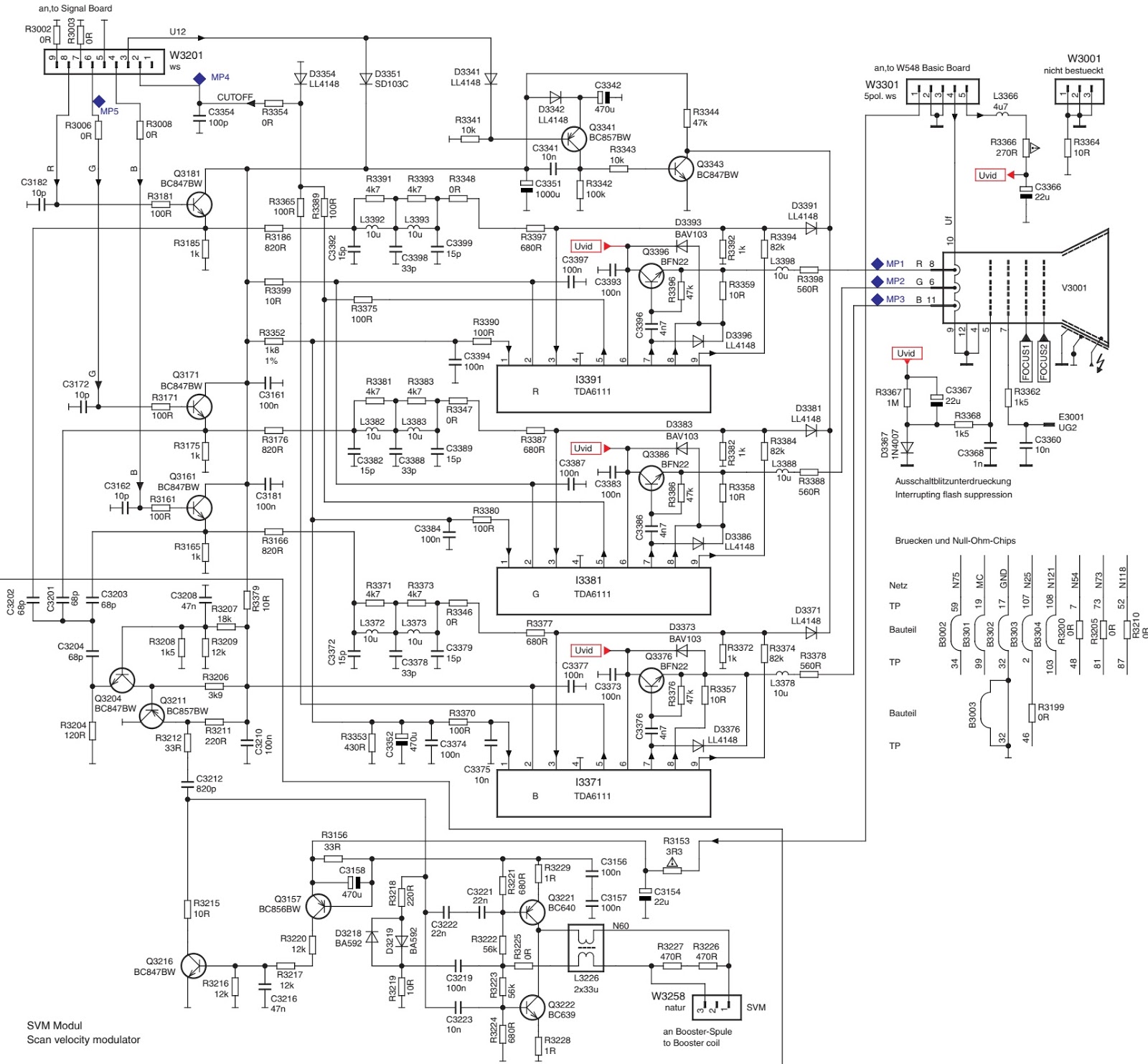
SMPS SCHEMATIC
Fixed voltage (or Auto voltage selectable) power supply circuit is used in this unit.  If Main Fuse (F1601) is blown , check to see that all components in the power supply circuit are not defective before you connect the AC plug to the AC power supply.  Otherwise it may cause some components in the power supply circuit to fail. The voltage for parts in hot circuit is measured using hot GND as a common terminal.
DIGITAL MAIN BOARD SCHEMATIC
The order of pins shown in this diagram is different from that of actual IC3104.  IC3104 is divided into eight and shown as IC3104 (1/8) ~ IC3104 (8/8) in this Digital Main Schematic Diagram Section.
Click on the schematics to magnify