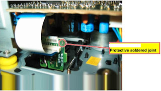
When removing the Laser pick-up or the Servo PCB, the Laser
pickup PCB must be provided with a protective soldered joint before unplugging
the connectors to avoid damage to the Laser diodes by static charges.
When
inserting the new Laser pick-up (CD drive mechanism) the soldered joint fitted
at the factory must be removed after the connectors are plugged in.
Exploded view
Power supply and Power amplifier schematic
Power amplifier and Power supply PWB
CD & Display Section Schematic

CD and Display section PWBs
Radio section PWB
Tape section schematic and PWB
Wiring diagram


