NEXT MA3200 Hi-Power
Stereo power supply schematic


NEXT MA3200 Hi-Power
Stereo CH1 Power amplifier schematic

NEXT MA3200 Hi-Power
Stereo CH2 Power amplifier schematic

NEXT MA3200 Hi-Power
Stereo power supply schematic
NEXT MA3200 Hi-Power
Stereo CH1 Power amplifier schematic
NEXT MA3200 Hi-Power
Stereo CH2 Power amplifier schematic


715G6550 P03 000 0020 Philips SMPS Schematic


RSA G7 820 8349 SMPS schematic

EAX65423701 LGP 3942 LED backlight supply board
schematic


VINTAGE
RADIO of (1975)

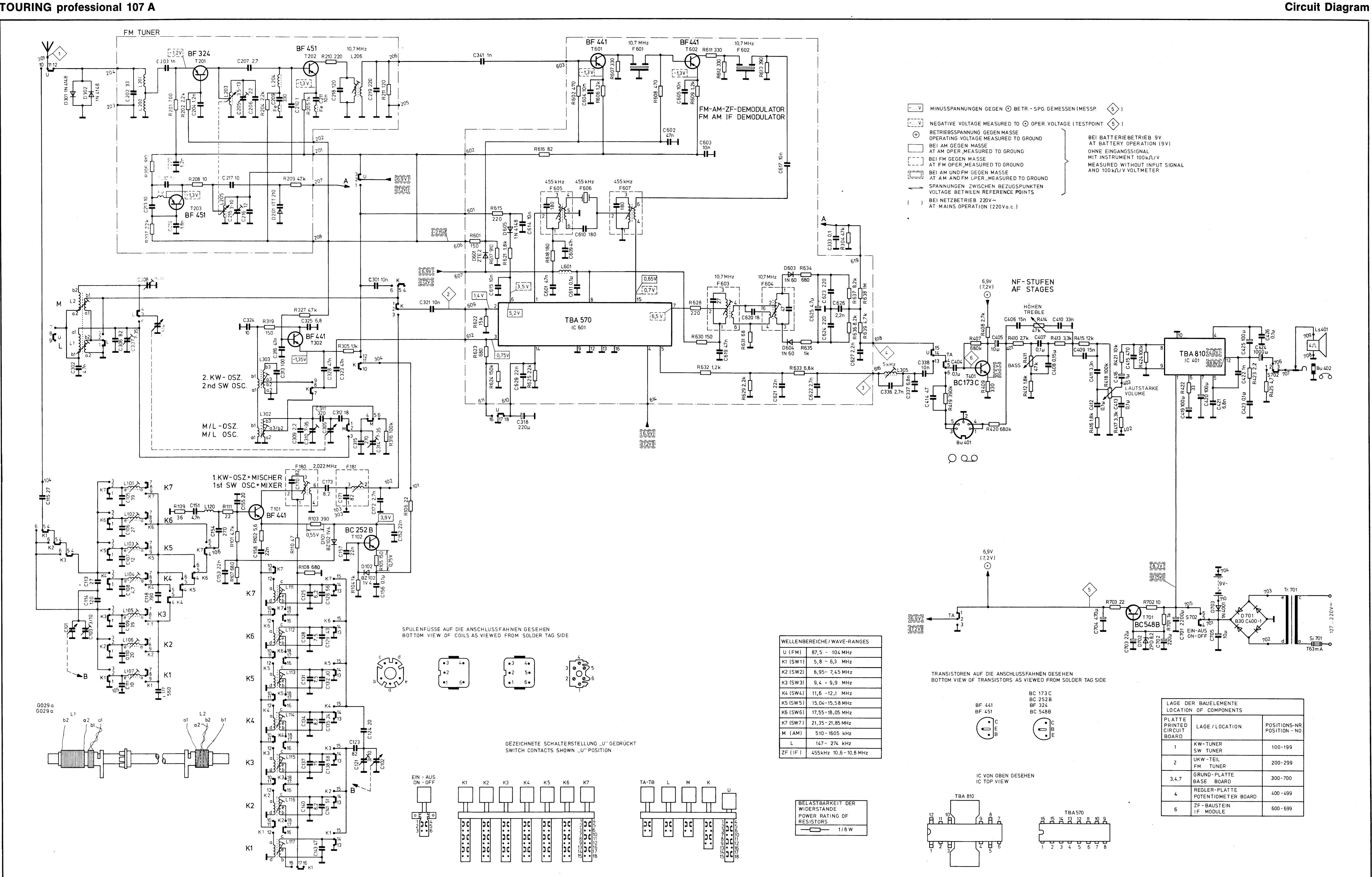
Touring professional
107 schematic

Printed circuit
boards of Touring Professional 107

Touring
professional 107A circuit diagram
Touring
professional 107A printed circuit boards

Drive chord assembly
- Touring 107

Drive chord
assembly – Touring 107A


Preset Memory
Patches:
1,273 + 256 (GM2)
Drum Kits: 19 + 9 (GM2)
Performances: 16
User Memory
Patches: 256
Drum Kits: 8
Performances: 128
Favorites: 100
Effects
Multi-Effects: 3 systems, 78 types
Chorus: 3 types
Reverb: 5 types
Sample Import Function
File Format
Audio
File: WAV (44.1 kHz, 16 bits)
AUDIO PAD Section
File Format
Audio File: WAV, AIFF, MP3
External Memory
USB Flash Memory (supports USB 2.0 Hi-Speed Flash Memory: Sold
Separately)
Other
Rhythm Pattern
Preset: 24 groups x 6
Arpeggio
Preset: 128
Controllers
Pitch Bend/Modulation lever
Sound Modify slider x 9
Disassembly Procedure
1. Remove screws a (13)
and b (5) in View 1 (Plane View (1)
2. Lift the top case slightly and detach the wiring connecting the main
board and the pedal board and the wiring connecting the keyboard and the panel
board.

Verifying the Version
Use the procedure
described below to verify the version of the application program. If the
version of the boot program is also required,
refer to Test Mode
Press the MENU
button. The MENU appears
Press the Cursor Left or
Right to select the Version Info, and then press Enter. The version information screen appears.
Formatting a USB
Memory Device
1. Insert a USB memory
device into the USB MEMORY connector.
|
2. |
Press MENU. |
3.
Press CURSOR Left or
Right to select UTILITY, then press ENTER. The UTILITY screen appears.
4. Press CURSOR Left or Right to select USB MEM FORMAT,
then press ENTER. Format USB
Mem? is displayed.
5. To execute formatting, press ENTER. To cancel it, press EXIT.
6. When formatting has finished, detach the USB memory device.
Data Backup Operations
Items Required
• USB memory device
(recommended: M-UF2G)
Procedure
1. Format the USB memory device (as described earlier).
|
2. |
Press MENU. |
3.
Press CURSOR Left or
Right to select UTILITY, and then press ENTER. The UTILITY screen appears.
4. Press CURSOR Left or Right to select BACKUP, and then
press ENTER.
NAME [ENT] flashes.
5. Press ENTER.
Backup is displayed.
6. To execute the backup operation, press ENTER. To cancel it,
press EXIT.
When the backup finishes, the display returns to the original screen.
Data Restore Operations
Procedure
1. Insert the USB memory
device containing the backed-up data into the USB MEMORY connector.
|
2. |
Press MENU. |
3.
Press CURSOR Left or
Right to select UTILITY, then press ENTER. The UTILITY screen appears.
4. Press CURSOR Right or Right to select RESTORE, then
press ENTER.
5. Press ENTER again.
RESTORE: [ENT] flashes.
6. To execute the restore operation, press ENTER. To cancel it,
press EXIT.
When the restore operation finishes, Completed. Turn off power. Is displayed.
7. Detach the USB memory device and reset the power.
Performing a Factory
Reset
|
1. |
Press MENU. |
2.
Press CURSOR Left or
Right to select UTILITY, then press ENTER. The UTILITY screen appears.
3. Press CURSOR Left or Right
to select FACTORY RESET, then press ENTER.
Factory Reset is displayed.
4. To execute the factory reset, press ENTER. To cancel it, press
EXIT.
When the factory reset has finished, Completed. Turn off power. Is displayed.
5. Reset the power.
Updating the System
Items Required
•
USB memory device (recommended: M-UF2G)
• Update program (obtained via Service Net)
Procedure
1. Format the USB memory device. (Refer to Formatting a USB Memory Device
2. Copy the update program (xps10_up.bin) to the root directory
of the USB memory device just described.
3. While the power to the unit is switched off, insert the USB memory device
just described into the USB MEMORY connector.
4. Hold down ENTER and switch on the power.
The update starts automatically.
*
Never switch off the power or detach the USB memory device while the update is in
progress. Doing so may cause malfunction.
When
finished. appears, the update has finished.
5. Detach the USB memory device and reset the power.
6. Verify that the version has been updated. (Refer to Verifying the
Version
Circuit Diagram (Main
Board)


Circuit Diagram (Panel
Board: 2/3)

Circuit Diagram (Panel
Board: 3/3)

Circuit Diagram (Master Volume Board)

.jpg)


