Yamaha T3n, T4n, T5n Power amplifier circuit diagram


VINTAGE
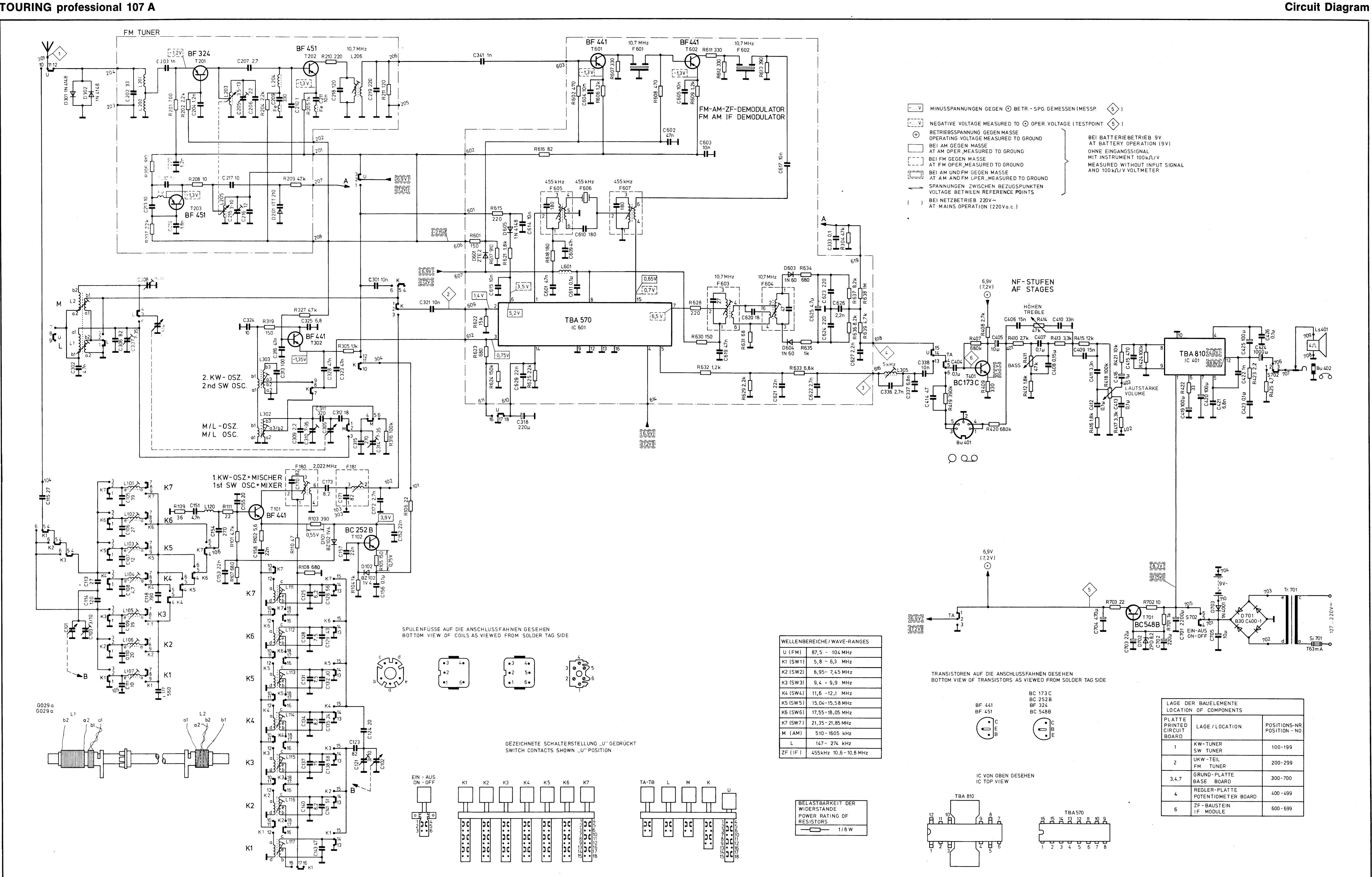
RADIO of (1975)

Touring professional
107 schematic

Printed circuit
boards of Touring Professional 107

Touring
professional 107A circuit diagram
Touring
professional 107A printed circuit boards

Drive chord assembly
- Touring 107

Drive chord
assembly – Touring 107A


Preset Memory
Patches:
1,273 + 256 (GM2)
Drum Kits: 19 + 9 (GM2)
Performances: 16
User Memory
Patches: 256
Drum Kits: 8
Performances: 128
Favorites: 100
Effects
Multi-Effects: 3 systems, 78 types
Chorus: 3 types
Reverb: 5 types
Sample Import Function
File Format
Audio
File: WAV (44.1 kHz, 16 bits)
AUDIO PAD Section
File Format
Audio File: WAV, AIFF, MP3
External Memory
USB Flash Memory (supports USB 2.0 Hi-Speed Flash Memory: Sold
Separately)
Other
Rhythm Pattern
Preset: 24 groups x 6
Arpeggio
Preset: 128
Controllers
Pitch Bend/Modulation lever
Sound Modify slider x 9
Disassembly Procedure
1. Remove screws a (13)
and b (5) in View 1 (Plane View (1)
2. Lift the top case slightly and detach the wiring connecting the main
board and the pedal board and the wiring connecting the keyboard and the panel
board.

Verifying the Version
Use the procedure
described below to verify the version of the application program. If the
version of the boot program is also required,
refer to Test Mode
Press the MENU
button. The MENU appears
Press the Cursor Left or
Right to select the Version Info, and then press Enter. The version information screen appears.
Formatting a USB
Memory Device
1. Insert a USB memory
device into the USB MEMORY connector.
|
2. |
Press MENU. |
3.
Press CURSOR Left or
Right to select UTILITY, then press ENTER. The UTILITY screen appears.
4. Press CURSOR Left or Right to select USB MEM FORMAT,
then press ENTER. Format USB
Mem? is displayed.
5. To execute formatting, press ENTER. To cancel it, press EXIT.
6. When formatting has finished, detach the USB memory device.
Data Backup Operations
Items Required
• USB memory device
(recommended: M-UF2G)
Procedure
1. Format the USB memory device (as described earlier).
|
2. |
Press MENU. |
3.
Press CURSOR Left or
Right to select UTILITY, and then press ENTER. The UTILITY screen appears.
4. Press CURSOR Left or Right to select BACKUP, and then
press ENTER.
NAME [ENT] flashes.
5. Press ENTER.
Backup is displayed.
6. To execute the backup operation, press ENTER. To cancel it,
press EXIT.
When the backup finishes, the display returns to the original screen.
Data Restore Operations
Procedure
1. Insert the USB memory
device containing the backed-up data into the USB MEMORY connector.
|
2. |
Press MENU. |
3.
Press CURSOR Left or
Right to select UTILITY, then press ENTER. The UTILITY screen appears.
4. Press CURSOR Right or Right to select RESTORE, then
press ENTER.
5. Press ENTER again.
RESTORE: [ENT] flashes.
6. To execute the restore operation, press ENTER. To cancel it,
press EXIT.
When the restore operation finishes, Completed. Turn off power. Is displayed.
7. Detach the USB memory device and reset the power.
Performing a Factory
Reset
|
1. |
Press MENU. |
2.
Press CURSOR Left or
Right to select UTILITY, then press ENTER. The UTILITY screen appears.
3. Press CURSOR Left or Right
to select FACTORY RESET, then press ENTER.
Factory Reset is displayed.
4. To execute the factory reset, press ENTER. To cancel it, press
EXIT.
When the factory reset has finished, Completed. Turn off power. Is displayed.
5. Reset the power.
Updating the System
Items Required
•
USB memory device (recommended: M-UF2G)
• Update program (obtained via Service Net)
Procedure
1. Format the USB memory device. (Refer to Formatting a USB Memory Device
2. Copy the update program (xps10_up.bin) to the root directory
of the USB memory device just described.
3. While the power to the unit is switched off, insert the USB memory device
just described into the USB MEMORY connector.
4. Hold down ENTER and switch on the power.
The update starts automatically.
*
Never switch off the power or detach the USB memory device while the update is in
progress. Doing so may cause malfunction.
When
finished. appears, the update has finished.
5. Detach the USB memory device and reset the power.
6. Verify that the version has been updated. (Refer to Verifying the
Version
Circuit Diagram (Main
Board)


Circuit Diagram (Panel
Board: 2/3)

Circuit Diagram (Panel
Board: 3/3)

Circuit Diagram (Master Volume Board)

Gradient CS34 tape-amplifier schematic
USED ICs STK4121, RC4558, HA12413,
MC1310

TCL 4056500 SMPS schematic

Applicable to Toshiba 21T01F, 21R01F, 21T01B, 14R01F, 14T01B,
14R01B, 21T01N, 21T01I, 21T01D, 14T01N, 14T01I, 14T01D
Factory Mode
1. Do not attempt
these adjustments in the Video Mode.
2. The Factory Mode adjustments are necessary when either the EEPROM (IC902) or
the CRT is replaced.
3. Do not tamper with the “Adjustment” screen of the Factory Mode menu. This
screen is intended only for factory use.
When EEPROM (IC902) Is Replaced.
1. When IC902 is replaced all adjustment data revert to initial values. It is
necessary to re-program this data.
2. After IC902 is replaced, warm up the TV for 10 seconds.
When CRT Is Replaced.
1. Make the following adjustments AFTER setting up after setting up purity and
convergence:
White Balance
Sub-Brightness
Vertical Center
Vertical Size
Horizontal Size
Fail Safe (This adjustment must be the last step).
2. If the EEPROM or CRT is replaced, set PVA to 40 (factory mode) and set SC as
follows.
14 inch : 18
21 inch : 24
Factory or Service Mode.
Procedure for
the “Adjustment” Mode.
1. This mode uses the standard remote control.
The Service Mode is activated by entering the following remote-control sequence
:
(1) DISPLAY→FACTORY.
(2) STAND-BY→DISPLAY→MENU→MUTE →POWER ON.
2. The “SERVICE (FACTORY)” message will be displayed. The Service Mode has
three components: ADJUST, OPTION and RESET.
3. Access the Adjustment Mode by pressing the “VOLUME” keys ( Up or Down). The
adjustment parameters are listed in the accompanying table, and selected by
pressing the CHANNEL keys (▲ ,▼).
4. Selection
sequences for the all system:
DOWN or UP key:
AGC>SCT>SBT>BLR>BLB>RG>GG>BG> VSL>VS>VA>HS>SC>CDL>STT>AKB>
PDL>NDL>PSR>NSR>VOL>LCO>TXP> MVOL>FMWS>AGCS>OMD>SCL>PWL>
AGN>PEK>ACL>FCO>SCBT>TSC
5. The VOLUME keys increase or decrease the adjustment values (stored in the non-volatile
memory) when Adjustment Mode is cancelled.
6. Cancel the Adjustment Mode by re-pressing the “FACTORY” or “Power OFF” key.
Initial data values

NOTE : PVS, PVA, PHS, parameters must be aligned using the 50Hz vertical-field rates.
Option Bytes
In the Service Mode, various can be selected via the Option Table. Example:

RESET
The Reset Mode is used during factory inspection.
Function Reset:
1. Picture Custom
2. Auto Volume Off
3. Color System Auto (option)
4. Blue Screen Off
5. Volume 10
6. CH. Skip Erased
7. CH. Lock Off
1.Usually, a color
TV needs only slight touchup adjustment upon installation. Check the basic
characteristics such as height, horizontal and vertical sync and focus.
2. The picture should have good black and white details. There should be no
objectionable color shading; if color shading is present, perform the purity
and convergence adjustments described below.
3. Use the specified test equipment or its equivalent.
4. Correct impedance matching is essential.
5. Avoid overload. Excessive signal from a sweep generator might overload the
front-end of the TV. When inserting signal markers, do not allow the marker
generator to distort test results.
6. Connect the TV only to an AC power source with voltage and frequency as
specified on the back cover nameplate.
7. Do not attempt to connect or disconnect any wires while the TV is turned on.
Make sure that the power cord is disconnected before replacing any parts.
Automatic Degaussing.
A degaussing coil is mounted around the picture tube, so that external
degaussing after moving the TV should be unnecessary. But the receiver must be
properly degaussed upon installation.
The degaussing coil operates for about 1 second after the power is switched ON.
If the set has been moved or turned in a different direction, disconnect its AC
power for at least 30 minutes.
If the chassis or parts of the cabinet become magnetized, poor color purity
will result. If this happens, use an external degaussing coil.
Slowly move the degaussing coil around the faceplate of the picture tube and
the sides and front of the receiver. Slowly withdraw the coil to a distance of
about 6 feet before removing power.
High Voltage Check.
CAUTION: There is no high voltage adjustment on this chassis.
The B+ power supply must be set to +125 volts (Full color bar input and normal
picture level).
1. Connect a digital voltmeter to the second anode of the picture tube.
2. Turn on the TV. Set the Brightness and Contrast controls to minimum (zero
beam current).
3. The high voltage should not exceed 27.5KV.
4. Adjust the Brightness and contrast controls to both extremes. Ensure that
the high voltage does not exceed 27.5KV under any conditions.
FOCUS Adjustment.
1. Input a black and white signal.
2. Adjust the tuning control for the clearest picture.
3. Adjust the FOCUS control for well defined scanning lines in the center area
of the screen.
Cathode Voltage Adjustment (Screen Adjustment)
1. Enter the FACTORY mode.
2. Select the G2-ADJUST.
3. Adjust the screen VR(on the FBT) so that ‘SCREEN ADJUST : NG(Red or Blue)’ becomes
‘SCREEN ADJUST : OK’.
When the color of ‘SCREEN ADJUST’ is red, the cathode voltage is low and when
blue, it is high.
4. Input a black
and white signal.
5. Fully demagnetize the receiver by applying an external degaussing coil.
6. Turn the CONTRAST and BRIGHTNESS controls to maximum.
7. Loosen the clamp screw holding the yoke.
Slide the yoke backward or forward to provide vertical green belt.
8. Tighten the convergence yoke.
9. Slowly move the deflection yoke forward, and adjust for the best overall
green screen.
10. Temporarily tighten the deflection yoke.
11. Produce blue and red rasters by adjusting the low-light controls. Check for
good purity in each field.
White Balance Adjustment.
Set up
1. Warm up the TV for at least 30 minutes in the Aging Mode (OSD White). This
mode is entered by entering the following sequence:
(Displaying AGING on the screen)
DISPLAY →FACTORY →FACTORY
2. Input a Toshiba pattern.
(b) Low-Light Adjustment
1. Set SBT to 3.5 ± 0.5 fL in the Factory Service Mode with using CA100.
(14inch : 2.5 ± 0.5fL, 21inch : 1.5 ± 0.5fL)
2. Adjust RG,BG so that the levels are suitable to each local area.
(c) High-Light
Adjustment
1. Set SCT to 35 FL (20”. 21”), 60 FL(14”) in the Factory Service Mode with
using CA100.
Center Convergence Adjustment
1. Warm up the receiver for at least 20 minutes.
2. Adjust the two tabs of the 4 pole magnets to change the angle between them.
Superimpose the red and blue vertical lines in the center area of the screen.
3. Adjust the Brightness and Contrast controls for a well defined picture.
4. Adjust the two-tab pairs of the 4 pole magnets, and change the angle between
them.
Superimpose the red and the blue vertical lines in the center area of the
screen.
5. Turn the both
tabs at the same time, keeping the angle constant, and superimpose the red and
blue horizontal line in the center of the screen.
6. Adjust the two-tab pairs of the 6-pole magnets to superimpose the red and
blue line onto the green. (Changing the angle affects the vertical lines, and
rotating both magnets affects the horizontal lines.)
7. Repeat adjustments 2~6, if necessary.
8. Since the 4-pole magnets and 6-pole magnets interact, the dot movement is
complex
RF AGC Adjustment
Set the AGC data to 33 (Factory Mode).
Sub-Color Adjustment
Set data to (Factory Mode).
Geometry Adjustment
SC →VS→VSL→HS
1. Input a lion head pattern (in the PAL channel).
2. Set the SC (S-Correction) as follows : 24 (21”),
24 (20”), 18 (14”) and VA 40 so that the lion head circle becomes oval.
3. Adjust with VSL (Vertical-Slope) so that the bottom margin of the picture is
4.
4. Adjust with VS (Vertical shift) so that the top margin of the picture is 4.

6. Adjust HS (using the width coil) so that the left and right margins of the picture are 5

Wiring diagram and schematic diagram


Toshiba PC-10X Stereo Cassette Tape
Deck Schematic

Kenwood KX-700 Stereo Cassette Deck
Schematic


Sanyo JA566 Parts list


