LG 29 inch CRT TV - schematic diagram and PWB - using STR6756 or STR6754 – switching power regulator - Models LG 29FX5R, LG 29FX5R-LA, LG 29FX5A, LG 29FX5A-LA
Printed circuit boards

Schematic diagram - Full

Schematic diagram - Split


LG 29 inch CRT TV - schematic diagram and PWB - using STR6756 or STR6754 – switching power regulator - Models LG 29FX5R, LG 29FX5R-LA, LG 29FX5A, LG 29FX5A-LA
Printed circuit boards
Horizont 42LE5131D SMPS (power supply board) schematic


RSAG7.820.5338 SMPS (power supply board) schematic -
Hisense 50H7GB1, 50H7GB, 50H7C


MIP988A-K2 SMPS (power supply board) schematic – AOC
LC42S05M, AOC LC42505M, LCD-42CA330


LGP42-13PL1
LED TV Power EAY62810501
schematic
On Condition : In a moment
of Power ON Signal activated, the current of 3.5V output should be limited
within 40mA(Max) at LCD TV condition for stability.
Do not turn “Power ON” Signal on at the load condition of 3.5V output, more
than 40mA.
* Total regulation for each
output circuit includes the results of input voltage variation, load variation,
warm-up drift and temperature change.
* Maximum input Wattage Rating: Under 85W
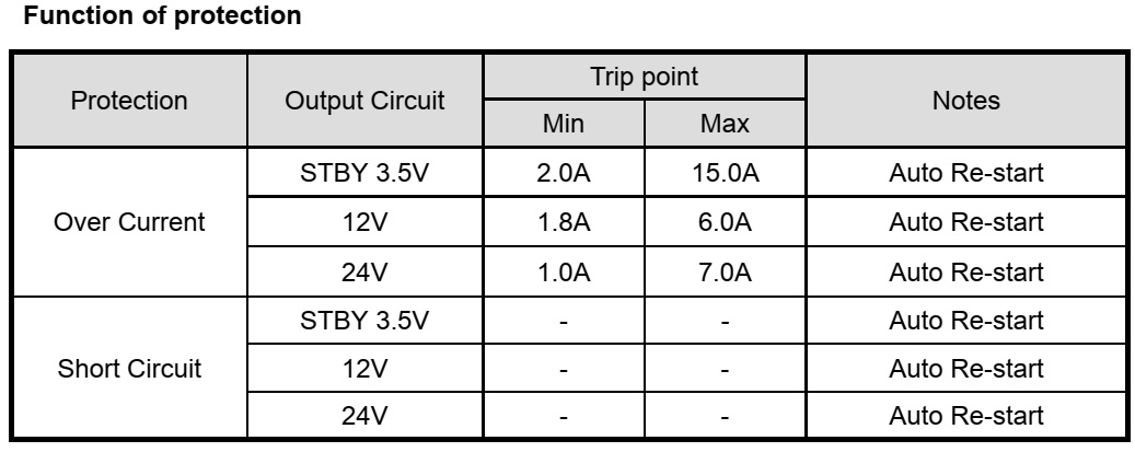
This Power Supply has
below-mentioned protections.
* Short circuit protection between different output terminals is not
considered.
* Trip point for over voltage indicates the operating point when the output
voltage slowly increases.
* The conditions of Over Current measurement Multi output (3.5V,12V,24V) is nominal load state except an over current measurement.
Connector voltages

Test methods

Block diagram

Schematic diagram

Elenberg LT-72602E Power board schematic


Elenberg 1402/2108/21F08/29F08 (Elenberg) 21SL39
(CAMERON) CRT TVs - full schematic, Factory menu (Service Menu)
Factory menu
Some
adjustments must be performed in the Factory menu. You can enter the Factory
menu in the following way:
1. Press the MENU button on
the remote control then press the Q.VIEW button on the remote control at least
5 times immediately.
2. Press the MENU buttons to select the desired Factory menu pages or press 0-9
number buttons to enter the Factory menu pages directly and then press the
PROG.+/- buttons to select the desired items.
3. Press the VOL+/- buttons to change the settings.
B+ Adjustment
Test
Equipment: Multifunction meter
1. Operate the TV set with AC 110-240V(50/60Hz).
2. Receive Television broadcast signal, set PICTURE to Normal mode.
2. Connect the multifunction meter + lead to C960 and GND. Adjust the RP950 until
the meter reading the proper DC value (model 1402/2108/21F08: B+=107±0.5Vdc;
model 21SL39: B+=115±0.5Vdc; model 29F08: B+=135±0.5Vdc)
High voltage check and filament voltage check
Test
Equipment: High voltmeter
1. Make sure AC power supply and +B are within pointed range before calibrating
high voltage.
2. Connect high voltmeter to anode (G4) of CRT.
3. Turn on the TV, set the BRIGHTNESS and CONTRAST to the minimum (zero beam
current), swap to AV mode (No any signal applied).
4. High voltage please see the related model BOM.
5. Filament voltage measured by virtual value meter please see the related
model BOM, usually within the range of 6.3±0.2Vrms.
Grid voltage adjustment
Enter into FAC3 and select
VG2, then adjust potentiometer to IN/OUT flash on the screen.
Receive PHILIPS five
circles pattern after settings finishing, set PICTURE to Normal mode.
RF AGC adjustment
1.
Receive a 60dBμ V gray scale signal(PAL or SECAM).
2. Enter Factory menu and select AGC TAKE OVER, then adjust it until the
picture noise is just disappeared.
FOCUS adjustment
1.
Receive five circles pattern, adjust the pattern to Normal mode.
2. Adjust focus potentiometer (horizontal output transformer) so that the
center and four corners of pattern are the best focus.
Horizontal scanning, vertical scanning and geometry correction adjustment
(adjust with PAL/SECAM and NTSC signal separately)
Receive five circles
pattern signal, enter into factory menu to call up FAC2.
VERT SLOPE 50(60) XX Adjust it so that horizontal midline of
the pattern superpose with the black edge of the pattern.
VERT SHIFT 50(60) XX Adjust it so that the pattern midline
superposes over CRT geometric center.
VERT AMPLE 50(60) XX Adjust it so that the picture vertical
reproduction display ratio is more than 92%.
S CORR 50(60) XX Adjust it so that upper pane and bottom
pan of the pattern are the same as the middle pane.
V.LIN.CTRL 50(60)
= 0
V. LINEARITY 50( 60)XX Adjust vertical
linear
VERT ZOOM 50(60) 25 Adjust vertical amplitude( fixed value 25)
2.
Call up FAC1
EW WIDTH 50( 60)XX Adjust it so that the
picture horizontal reproduction display ratio is more than 92% (H- size
adjustment).
HOR.SHIFT 50( 60) XX
Adjust it so that the left half is symmetrical with the right half (H. CEN
correction).
EW PARABOLA 50( 60) XX Adjust
it so that parallelogram will be transformed to rectangle or trapezium (Receive
cross hatch signal)(Parallelogram correction).
TRAPEZIUM 50( 60) XX Adjust
it so that trapezium distortion is just disappeared (Receive cross hatch
signal)(Trapezium).
UC PARABOLA 50( 60) XX Adjust
it so that upper corner (left and right) vertical line are straight line
(Receive cross hatch signal)(Upper corner pincushion).
LC PARABOLA 50( 60)XX Adjust it so that bottom corner (left and
right) vertical line are straight line (Receive cross hatch signal)(Bottom
correction pincushion)
HOR.BOW 50( 60) XX Adjust it so that vertical line is the
straight line.(Receive cross hatch signal) (Bow correction).
PARALLEL 50( 60) XX Adjust
it so that left and right line are straight lines (Pincushion correction).
White balance adjustment (PAL or SECAM signal)
1.
Enter into menu firstly and set COLOR mode to normal.(9300K)
2. Enter into AV mode and receive left black right white signal which with
color sync signal.
3. Plug XS805, adjust it automatically with white balance adjustment software,
enter into factory menu when adjustment is OK, then enter into FAC 6、 FAC 7, FAC 8 menu to check the
following data are consistent with data in computer.
Standard: Color temperature 9300K ( X=0.284
Y=0.299) FAC 6
Cold color: Color temperature 12000K( X=0.272
Y=0.279) FAC 8
Warm color: Color temperature 6500K ( X=0.313
Y=0.329) FAC 7

SCHEMATIC DIAGRAM


CHANGHONG SMPS (POWER SUPPLY SCHEMATIC)

PHILIPS VES15 1HE SMPS (SCHEMATIC)
17IPS61-3p1 19", 24" and 28" Slim Integrated Power Supply


17IPS71P-R4 – 32, 40 and 48 inch power supply


