National/Panasonic RQ92 cassette recorder circuit diagram
Used ICs:
AN6552, MN3007, BA3702, TA7240AP


National/Panasonic RQ92 cassette recorder circuit diagram
Used ICs:
AN6552, MN3007, BA3702, TA7240AP
(Hybrid) color TV - Admiral Chassis K10 - Vintage TV - 1974. Spare component availability will be rare. Just compare this with modern TV circuits, and feel how much the field of electronics have developed. There was no integrated circuit (ICs) at that time.
The circuit consists of both tubes and transistors (Hybrid type). Tubes are used at its horizontal output and video output stage circuit. Most of these tubes are not available now. Moreover the circuit boards are dangerous to handle, due to very high voltages present on them, while the set works. The picture tube is a Shadow Mask type, need very high voltage, in the range between 27 KV to 30KV, and have more than 33 alignment points.
More to say, these sets are very costlier at that time, only very rich ones can afford it. Actually, luxurious piece at that time too.
This was the time, that I entered into this field of electronics as a professional service technician. I'm 71 now, and still continues.

Layout – PWB

Schematic - Full


Nominal output
power: 4 x 50W:
2 x 100W
CONTROL / DISPLAY SCHEMATIC DIAGRAM
PT6315, HRM557BC5109, HT48R05


MAIN SCHEMATIC DIAGRAM: 1 OF 3
STA308A, STA515, BA4558F

MAIN SCHEMATIC: 2 OF 3
ES6603SF, BA5954FP, CS5340-C7, BA6289F,
SN74AHC1GOBDBV, ES6698FD, M29W160ET70NG

MAIN SCHEMATIC: 3 0F 3
BU4052BF

MEMORY CARD READER SCHEMATIC DIAGRAM
GL816, 74VHC125M, 74LCX138M, 74LVX74MTR,
CFCARD4312-23xxx

POWER SUPPLY [SMPS] SCHEMATIC DIAGRAM
L6565, VIPer53

Sharp 14D1-S/G/W and 14D2-S/G - 18 system color
television
Service mode and adjustments
This model's setting are adjusted in two different ways: through the I2C bus control and in the conventional analog manner. The adjustments via the I2C bus control include preset-only items and variable data.
CAUTION: Make sure TV Set is in "Normal Condition" before switch to Service Mode for adjustment.
Setting the service mode by the microprocessor
Short JA 137 & JA 138 for 1 second and release to switch to the service mode position, and the microprocessor is in input mode. (Adjustment through the I2C bus control). (Use JWS Key to set as well).
Press the CH DOWN / UP key on the remote controller to get ready to select the mode one by one.
Press the CH DOWN / UP key on the remote controller to select the modes reversibly one by one.
Using the VOLUME UP/ DOWN key on the remote controller, the data can be modified.
Short JA 137 & JA 138 for 1 second and release to switch to the normal mode (OFF) position, and the microprocessor is in out of the service mode.
Factory Presetting.
Short JA 137 & JA 138 then turn "ON" the main power and release to switch to the Service Mode position.Initial values are automatically preset, only when a new EEPROM is used (Judge with the first 4 bytes )
The initial data are preset as listed here.
Make sure the data need modify or not (Initial data).
Note: Once the chassis has been assembled together and ready to be POWER ON for the FIRST TIME, make sure to short JA137 & JA138 to switch to the service mode position first and then turn on the main power switch.
If haven't done this initiation, it may possibly generate excessive Beam current.
AFTER SHORT JA 137 & JA 138 ,AND TURN ON THE MAIN
POWER SWITCH,READ DATA FROM EEPROM ADDRESS 00H ~ 03H,AND COMPARE TO THE LIST
BELOW, IF DIFFERENT, INITIALIZE THE EEPROM.


Direct Key-in for Service Item in Service Mode


INITIAL SETTING
In service mode,
After execute select POS 1, store the following tuning data in E2PROM.
Note: All sound system of following channels will be set to B/G or I after
pressing INITIAL KEY 2, 3 or 4.

Shipping setting and checking

GA1 Hotel mode application
How to enable or disable the hotel mode.
Press the R/C [function] (1) key until language selection appear, withing five second press the [one/two digit] {2} key and keep pressing it for five second, then you can cee the hotel mode with four digits password.
Key in the four digit password number 1,3,7,9, then the hotel mode will be enabled, and you can switch on/off the hotel mode by using R/C [volume up/ volume Dn {3} key.
It is recommended before set the hotel mode, is better to chose ch1 & set S-Vol level up to 75% full scale. After set hotel mode, starting channel will be always ch-1 and maximum sound out will be set the half of the full scale.
If you set hotel mode in AV, starting channel will be the last channel which you received before power off [same as normal operation.
Condition
When using the hotel mode, user can cantrol contrast, brightness, sharpness and tint function.
You can’t use:
Preset mode
Fine tuning
Skip mode
System selection
The other function is allowed to be used.
SCHEMATIC DIAGRAM:CRT UNIT and SCHEMATIC
DIAGRAM:HEADPHONE UNIT

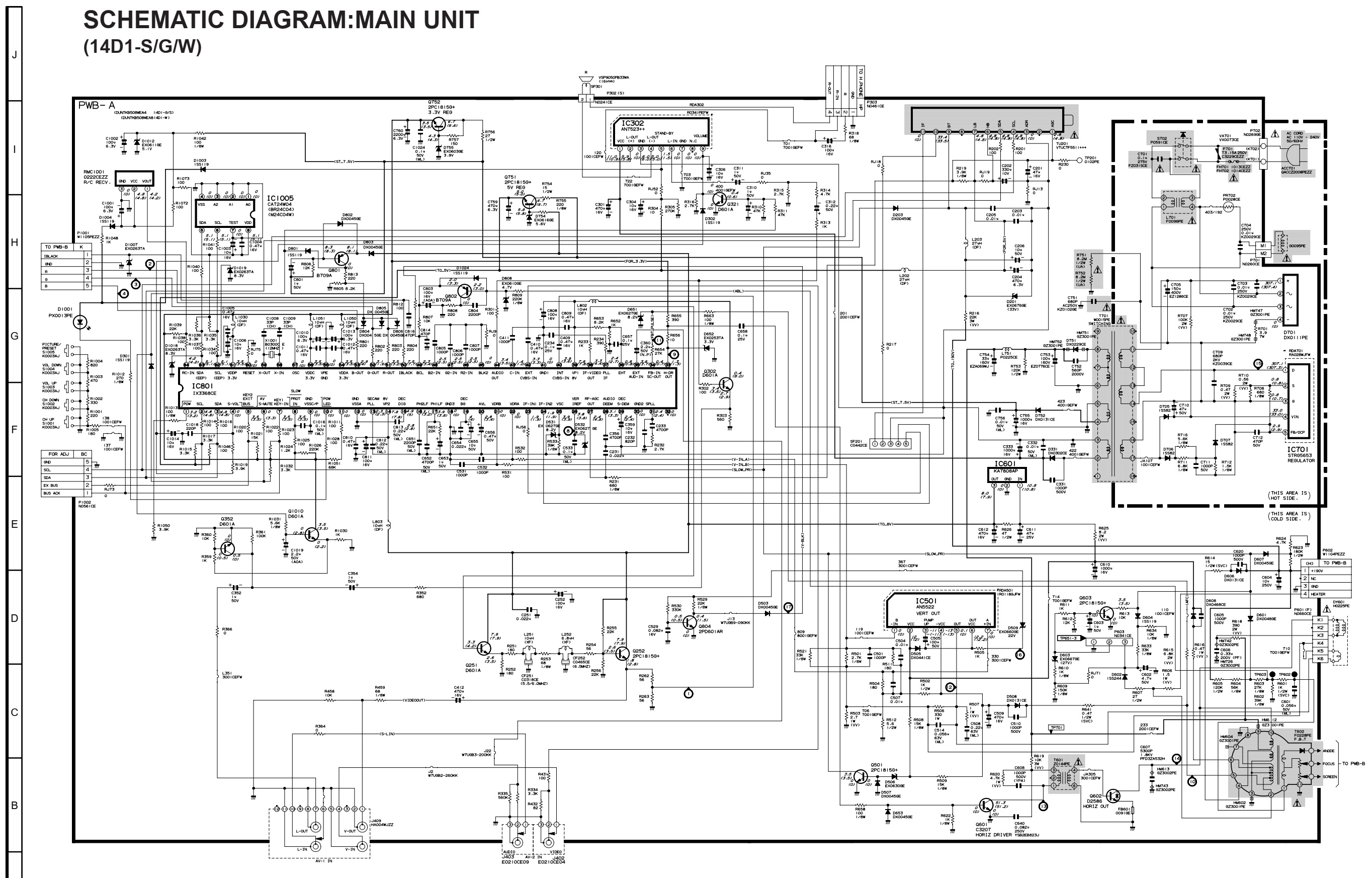
SCHEMATIC DIAGRAM:MAIN UNIT (14D1-S/G/W)
SCHEMATIC DIAGRAM:MAIN UNIT (14D2-S/G)

PWB


Display section schematic

Head preamp section schematic

Digital processor section schematic

Main amplifier section schematic

Philips 32PFL3200 POWER SUPPLY (SMPS) Schematic diagram – 715G4831


Philips 42PFL3300 POWER SUPPLY (SMPS)
Schematic diagram – 715G4922


715G3936 & 715G3967

Philips 39PFL5046 POWER SUPPLY (SMPS) Schematic diagram


Vintage Cassette Radio Recorder – National Panasonic RQ
432S schematic, layout and dial cord setting.

The main fault that can occur to this set is the
tuning drift occurs when climate changes. The
inductance of TR54 and or TR56 may change. Replace them if this type of fault occurs. If you blow some hot air over these coils, it may work properly, the fault will come back after some time. There is no remedy than changing them.
At the amplifier stage, C19 and C20 [capacitors
connected between collector base of the output transistors] may get leak. Resulting distorted audio output. The company have used steroflex capacitors
there. I’ve replaced both of them with
disc ceramic [250VDC] type, and going fine.
The C34 [1000MFD-10V] should be checked for its
capacitance. It is best to replace
it. Sound distortion can occur if this
capacitor is damaged.
C32 [220MFD 10V] can also be problematic. Replace it with a new one.
I own this model set, which bought at mid of 70s, I
presume, is working fine till time.
There is no more problems can occur to this set.
Amplifier section schematic


Philips 40PFL3606 power board schematic


AOC L42H961 power board 715G3351 schematic


Samsung power board BN44-00262A schematic

