DC-DC CONVERTER
This block provides adjustable output voltages of 9.2V, -6V, 18V and 3 to 4V for the panel. It consists of a Q114 transistor and power switch IC I108 (AIC 1526-1). When DC_ EN signal is high, then Q114 is activated and send one signal to activate I108. At this time I108 will send 200KHz 12V PWM to Q106, Which is connected with L111, Q106, D203 and C308, to boost 5V to 9.2V. And I108 offers the adjustable voltage of 3V to 4V. By sending out pulses from pin 2 and pin 16 of I108 to double voltage circuit consisting of C301, D201, D202 and C303, leaner regulator with Q105, would output –6V, 18V output id created, according to the rule of –6V creation.


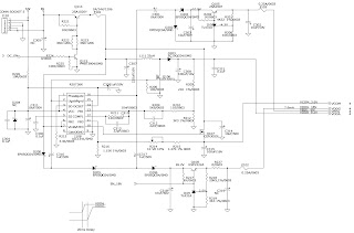


This block provides adjustable output voltages of 9.2V, -6V, 18V and 3 to 4V for the panel. It consists of a Q114 transistor and power switch IC I108 (AIC 1526-1). When DC_ EN signal is high, then Q114 is activated and send one signal to activate I108. At this time I108 will send 200KHz 12V PWM to Q106, Which is connected with L111, Q106, D203 and C308, to boost 5V to 9.2V. And I108 offers the adjustable voltage of 3V to 4V. By sending out pulses from pin 2 and pin 16 of I108 to double voltage circuit consisting of C301, D201, D202 and C303, leaner regulator with Q105, would output –6V, 18V output id created, according to the rule of –6V creation.
Inverter
In order to drive the CCFLs embedded in the panel module; there is a ROYER inverter to convert to convert the input 12V up to hundreds of AC voltage output. The inverter is formed by symmetric, in order to drive the separate lamp modules.
The input stage consists of a PWM controller, buck choke, and switching MOSFET to convert DC input into AC output. The output stage consists of a tuning capacitor, transformer, push-pull transistor pair to boost ac output up to hundreds of voltage. And one resister is serial to lamp for output current feedback. A 5-pin connector is the only interface to control the inverter. Pin 1 is 12V input, Pin 2/4 is the returns, pin3 is the control of output current, and pin 5 is the enable/disable control.
Audio Output

DC-DC converter

Panel Power

MCU

MVZ

Scalaring
controller
MascotV scalar is a highly integrated solution that combines a high performance ADC with an advanced image processing controller. Using advanced image scaling algorithms, Mascot V has intelligently adaptive sub-algorithms that will automatically optimize the display quality for different images – the text is sharper and the graphics is smoother. The built-in analog interface includes a 160Mhz, 8-bit 3-channel ADC, preamplifier, and VGA, allowing seamless support to resolutions from VGA to XGA. MascotV also offers other integrated functions such as an internal OSD that supports all languages, and build-in line buffers that allows support to a wide range of LCD panels. The scalar implements four advanced display technologies:
1. Sampling RGB input signals by fully integrated triple-channel ADC, PLL, and pre-amplifier
2. Automatically calibrate for vertical and horizontal alignment to center display and phase calibration
3. High-quality advanced scaling: Enhanced and adaptive scaling algorithm for optimal image quality
4. One and two pixels per clock panel support: Up to 24 bits per pixel.
The panel interface consists of 48-bit panel data bus, Start Pulse(STH1) and Clock (CLKH), Polarity(POL)/Latch pulse(LP) for source driver IC, Start pulse(STV1) and Clock(CLKV) for gate driver IC, and Data inversion control(HMSO/HMSE) for odd/even pixel bus and the power supply (+3.2V, +3.45V<adjustable>,+9.2V, +18Vand-6V) for panel driver IC use.


