Tuesday, February 23, 2021

Sharp 14D1 and 14D2 Service mode, service adjustments, Hotel mode, Schematic diagram


Sharp 14D1-S/G/W and 14D2-S/G - 18 system color television

Service mode and adjustments

This model's setting are adjusted in two different ways: through the I2C bus control and in the conventional analog manner. The adjustments via the I2C bus control include preset-only items and variable data.  

CAUTION: Make sure TV Set is in "Normal Condition" before switch to Service Mode for adjustment.

Setting the service mode by the microprocessor

Short JA 137 & JA 138 for 1 second and release to switch to the service mode position, and the microprocessor is in input mode. (Adjustment through the I2C bus control). (Use JWS Key to set as well).

Press the CH DOWN / UP key on the remote controller to get ready to select the mode one by one.

Press the CH DOWN / UP key on the remote controller to select the modes reversibly one by one.

Using the VOLUME UP/ DOWN key on the remote controller, the data can be modified.

Short JA 137 & JA 138 for 1 second and release to switch to the normal mode (OFF) position, and the microprocessor is in out of the service mode.

Factory Presetting.

Short JA 137 & JA 138 then turn "ON" the main power and release to switch to the Service Mode position.Initial values are automatically preset, only when a new EEPROM is used (Judge with the first 4 bytes )

The initial data are preset as listed here.

Make sure the data need modify or not (Initial data).

Note: Once the chassis has been assembled together and ready to be POWER ON for the FIRST TIME, make sure to short JA137 & JA138 to switch to the service mode position first and then turn on the main power switch.

If haven't done this initiation, it may possibly generate excessive Beam current.

AFTER SHORT JA 137 & JA 138 ,AND TURN ON THE MAIN POWER SWITCH,READ DATA FROM EEPROM ADDRESS 00H ~ 03H,AND COMPARE TO THE LIST BELOW, IF DIFFERENT, INITIALIZE THE EEPROM.


Direct Key-in for Service Item in Service Mode


INITIAL SETTING

In service mode, After execute select POS 1, store the following tuning data in E2PROM.
Note: All sound system of following channels will be set to B/G or I after pressing INITIAL KEY 2, 3 or 4.


Shipping setting and checking


GA1 Hotel mode application

How to enable or disable the hotel mode.

Press the R/C [function] (1) key until language selection appear, withing five second press the [one/two digit] {2} key and keep pressing it for five second, then you can cee the hotel mode with four digits password.

Key in the four digit password number 1,3,7,9, then the hotel mode will be enabled, and you can switch on/off the hotel mode by using R/C [volume up/ volume Dn {3} key.

It is recommended before set the hotel mode, is better to chose ch1 & set S-Vol level up to 75% full scale.  After set hotel mode, starting channel will be always ch-1 and maximum sound out will be set the half of the full scale.

If you set hotel mode in AV, starting channel will be the last channel which you received before power off [same as normal operation.

Condition

When using the hotel mode, user can cantrol contrast, brightness, sharpness and tint function.

You can’t use:

Preset mode

Fine tuning

Skip mode

System selection

The other function is allowed to be used.

SCHEMATIC DIAGRAM:CRT UNIT and SCHEMATIC DIAGRAM:HEADPHONE UNIT


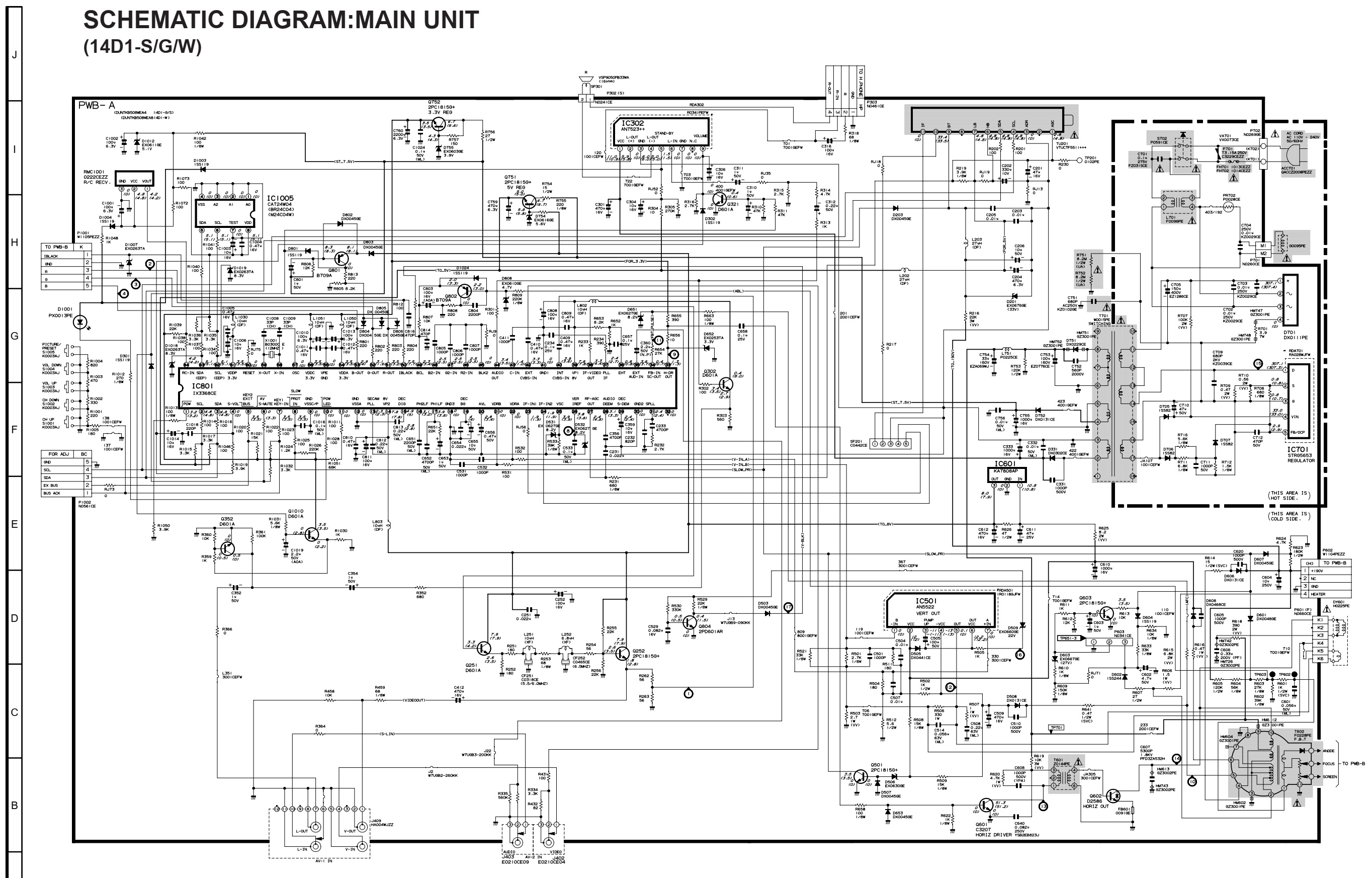
SCHEMATIC DIAGRAM:MAIN UNIT (14D1-S/G/W)


SCHEMATIC DIAGRAM:MAIN UNIT (14D2-S/G)


PWB


Saturday, February 20, 2021

CCE A-650 - LOGIC DECK-TUNER-DVD player 1000watts PMPO - Schematic


Display section schematic

Head preamp section schematic

Digital processor section schematic

Main amplifier section schematic

Sunday, February 14, 2021

Philips 39PFL5046, Philips 42PFL3300 and Philips 32PFL3200 LCD TVs – Power supply (SMPS) schematic diagrams

 Philips 32PFL3200 POWER SUPPLY (SMPS) Schematic diagram – 715G4831

Philips 42PFL3300 POWER SUPPLY (SMPS) Schematic diagram – 715G4922

715G3936 & 715G3967

Philips 39PFL5046 POWER SUPPLY (SMPS) Schematic diagram

Wednesday, February 10, 2021

RQ432S National Panasonic circuit diagram. Vintage Radio Cassette Recorder


Vintage Cassette Radio Recorder – National Panasonic RQ 432S schematic, layout and dial cord setting.

The main fault that can occur to this set is the tuning drift occurs when climate changes.  The inductance of TR54 and or TR56 may change.  Replace them if this type of fault occurs. If you blow some hot air over these coils, it may work properly, the fault will come back after some time.  There is no remedy than changing them.

At the amplifier stage, C19 and C20 [capacitors connected between collector base of the output transistors] may get leak.  Resulting distorted audio output.  The company have used steroflex capacitors there.  I’ve replaced both of them with disc ceramic [250VDC] type, and going fine.

The C34 [1000MFD-10V] should be checked for its capacitance.  It is best to replace it.  Sound distortion can occur if this capacitor is damaged.

C32 [220MFD 10V] can also be problematic.  Replace it with a new one.

I own this model set, which bought at mid of 70s, I presume, is working fine till time.  There is no more problems can occur to this set.  

Amplifier section schematic

Tuner section schematic

PCB layout
Dial chord setting


Thursday, February 4, 2021

BN44-00262 Samsung, 715G3351 AOC L42H961 and Philips 40PFL3606 POWER SUPPLIES SCHEMATICS


Philips 40PFL3606 power board schematic

AOC L42H961 power board 715G3351 schematic


Samsung power board BN44-00262A schematic


Monday, January 25, 2021

Grundig THARUS 38 inch LCD TV 38-9210 - How to enter the service mode, service mode adjustments, full schematic


Service Menu

Calling up and working with the service menu
– Press the »AV/OK« and »POWER« buttons on the TV set at the same time.
The FACTORY menu (service menu) is displayed on the picture screen.

– Select the desired alignment function (row) using the »P–« or »P+« button on the TV set or on the remote control.
– Activate the alignment or change the settings using the »
L–« or »L+« button on the set, or the » + « or » - « button on the remote control.
– Call up the main menu using the »
i« button.

Exiting the service menu
Repeatedly press the »i« button on the set or on the remote control until the menu disappears, or press the »OK« button on the remote control.

Alignment functions
Note:
The functions of the FACTORY ADJ menu item are relevant for the alignment. Via the FACTORY ADJ menu item, the values for the MX88L281 1, AD9884 1, AD9884 2, and VPC3230 are automatically adjusted. The values indicated for MX88L281 1, AD9884 1, AD9884 2, VPC3230 serve as medium and basic values and are to be changed only if required.

FACTORY ADJ

CLOCK DELAY
– Connect a computer with installed "Acrobat Reader" to the SVGA socket.
Observe the setting of the graphics card.
– Call up the "
1bit" test pattern in full picture mode of "Acrobat Reader" on the computer.
- Change the setting (typ. 15) until the picture is stable and the vertical lines are no longer fringed.

AUTO COLOR GAIN
– Connect a computer with installed "Acrobat Reader" to the SVGA socket.
Observe the setting of the graphics card.
– Call up the "
Colorbar" test pattern  in full picture mode of "Acrobat Reader" on the computer.
If the chromatic regions in the bottom part of the test pattern should be coloured, repeat the alignment.
– After activating the alignment function, the alignment is carried out automatically.

OPTION – X3 – INVERT
– For the OPTION function, "X3 – INVERT" must be set.

TTX Local: PAN EUROPE
– For the TTX Local function, the following settings for country-specific
Teletext special characters are possible:
PAN EUROPE
CYRILLIC-RUSS
GREEK
ARAB
CYRILLIC-UKRA

TTX E/W: WEST
– For the TTX E/W function, it is possible to select between the
country-specific Teletext settings EAST and WEST.

MX88L281 1 (IC601)
– CONTRAST 25 (0…31)
– BRIGHT 15 (0…31)
– EDGE FILTER 0 (-63…+63)
– CLOCK DELAY 15 (0…15)
– EXPAND ON

AD9884 1 (IC360)
Note: this function can only be called up in PC mode.
– RED GAIN 127 (0…255)
– GREEN GAIN 127 (0…255)
– BLUE GAIN 127 (0…255)
– RED BIAS 31 (0…63)
– GREEN BIAS 31 (0…63)
– BLUE BIAS 31 (0…63)
– AUTO TRACKING (automatic function)
CLOCK 125 (0…250)
PHASE 15 (0…31)
– AUTO COLOR GAIN (see Point 3.1.2)

AD9884 2 (IC360)
Note: this function can only be called up in PC mode.
– INIT VCO CURRENT (automatic function)
SUB C VCO 1 (0…3)
SUB C CHG CURRENT 4 (0…6)

AD3230 (IC301)
Note: this function can only be called up in TV mode.
– CONTRAST 52 (0…63)
– BRIGHTNESS 9 (0…15)
– PEAKING 0 (0 / 1)
– CIP CONTRAST 7 (0…15)
– CIP BRIGHT 7 (0…15)

Block Diagram

Block diagram of the main board

PWBs


Schematic diagram