Thursday, August 25, 2016

Staner BS 150 Bass Amplifier - circuit diagram

BS150 - Staner - Guitar Bass Amplifier - schematic
Schematic

Wednesday, August 24, 2016

Sanyo MCD ZX700F Circuit diagram – Bassxpander

TUNER ADJUSTMENTS

Use a plastic screw driver for adjustments.
Adjust the intermediate frequency of AM and FM to the frequency of ceramic filter.
Set of unit
Supply voltage : DC 12V
Speaker : 32
Function switch : RADIO
Circuit diagram - Micom
Audio
Radio
CD
PWB

Changhong PF29GA18A – How to enter service mode – circuit diagram – 29 inch color TV.

ETA-1D chassis is applied in PF29GA18A series.
By use of Toshiba V/C/D-MCU 2IN1 IC for TV small signal processing and bus control, the chassis enables TV tuning, adjustment, control and picture correction, featuring
high-integration, high-performance-to-price ratio and high-reliability and compact circuit with fewer external components. The chassis, widely used in small and medium TVs,
provides much more convenience for manufacturing and technical service. It includes:
2IN1 IC 8897PSBNG-4VB6 for PAL/NTSC small signal processing and bus control [TMPA8897CMANG /CPANG/CRANG /CSANG]
EEPROM AT24C16 for data memory
LA78041 for vertical output power amplifying
LA42102 for audio power amplifying
TA1343N for audio processor
FSCQ1265RTYDTU for power circuit adjustment and control.
BSC68DG (FBT)
Mask ROM: TMPA8897CPBNG (ROM size: 48k)
Mask ROM: TMPA8897CRBNG (ROM size: 56k)
Mask ROM: TMPA8897CSBNG (ROM size: 64k)
OTP ROM: TMPA8897PSBNG (ROM size: 64k)
Color systems: PAL, NTSC
Sound systems: D/K B/G I M
236 programs preset
AV stereo
I2C bus control
Electronic program table
Intelligent lock
Biorhythm
Calendar inquiry.
To enter the DESIGN/SERVICE mode
Set the volume to 0.
Press and hold the MUTE button on the remote control, and press the MENU button on the TV to enter the SERVICE mode.
In this case, blue “D” is displayed on the upper center of the screen.
To exit from the D mode, turn off the TV set by the POWER button on the remote control.
Caution: The user service mode adjustment can be changed only when service personnel adjust the whole set data during servicing. As the control data have dramatic effects on functions and performance of the TV, service personnel should not tell user how to enter the SERVICE mode to avoid improper data settings.
Circuit diagram
It’s impossible to check the power part separately from the main chassis board as the part is mounted on the main chassis board. The power components, etc. should be checked for burnout when power-on. If burned out, do not power on the TV again until the cause is found out.
SMPS and system-chroma junge circuit - Split
Click on the pictures to zoom in

Sunday, August 21, 2016

Phonic Powerpod 620 – circuit diagram – Powered Mixer

Circuit Diagram (Schematic) - Phonic Powered Mixer - PowerPod-620
Controls
Circuit diagram

Philips 21PT9457- 55 – Flat CRT TV. Circuit diagram and adjustments

This chassis does not contain a specific Service mode. The Services and device setting can be made via Mode the Technical Assistance Factory.
There is no program on TV
Check method: Check the closed circuit to the tuner IC image encoder for detecting whether components defective. Or check if the resistance R117, R118, R203 and R204 has increased may cause the problem.
No Good Picture or Dual Image
Check the signal IF1 / IF2 to Q101 and relevant circuit. In this case the problem can be Q101 and / or SAW 101.
No Picture or Color Correct
• Check the circuit IC201 to RGB.
• Check the welding IC and physical damage of the relevant circuit or check defective capacitors.
Image with White Line Horizontal and Audio
Check voltage supply of vertical IC301 and circuit relevant, and check the vertical sync signal IC201.
Control Evil Operation Remote
Check voltage at pin 64 of IC201. The normal value should be 5.15V. If correct check the welding connections front control panel. If it cannot be resolved check remote control, remote transmission or crystal diode are in good condition.
Without audio
Check audio power IC (IC402) and relevant circuit.
Check BTSC panel, the power of the IC801 and signal output pins 21:27 this IC. Do not delete the IC801 and / or IC402 may be faulty. If necessary, replace the speakers.
Bad Quality Audio
Check the audio system after searching the channel that should be NTSC or AUTO. If the problem persists, check the panel circuit is good chassis or not.
Main voltage adjustment
To adjust the main voltage, connect a voltage meter the diode D610 and cathode VR601 adjustment to the voltage 110 V + -0.3V.
Circuit diagram (Schematic) and PWB [Click on the pictures to magnify]
SMPS (split)
Sub-woofer
Block diagram
Adjustment mode flow chart
Factory Mode adjustment procedure
Software settings
Place evenly-matched in the MENU mode (the default mode) as follows (see "Factory Mode" figure on the next page:
> Press the [i +] keys, "smart sound" and "smart picture" for enter the factory menu.
> Press the [i +] again and "ADJUST" appears on screen.
> Press the number keys to enter the set page, press the Up/Dn keys to change the items that have been set, press the Left/Right keys to adjust their values .
> Press [i +] to exit the factory mode.
The different parameter settings are described above.

Friday, August 19, 2016

Philips AZ1010 – CD Radio Cassette Recorder – Circuit Diagram

Tuner board
Combi board
Click on the schematics to zoom in

Sony MDS S9 – Circuit diagram – Minidisc Deck

MD mechanism type: MDM-7A

Optical pick-up name: KMS-260B
Display Board
BD Board
Main Board
Click on the schematics to magnify


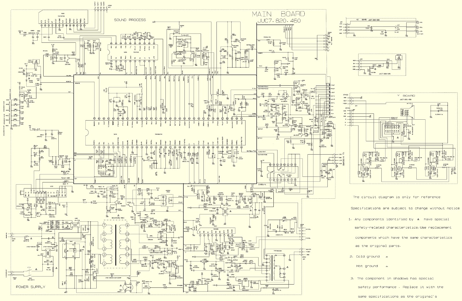
Teledex 21NF55 – Teledex 21PF93 – How to enter service mode – Schematic diagram – CRT Television

DESIGN/SERVICE mode
To enter the USER SERVICE mode
Caution: The user service mode adjustment can be changed only when service personnel adjust the whole set data during servicing. As the control data have dramatic effects on functions and
performance of the TV, service personnel should not tell user how to enter the SERVICE mode to avoid improper data settings.
Set the volume to 0. Then press and hold the MUTE button on the remote control, and press the MENU button on the TV to enter the SERVICE mode. (In this case, the S mode cannot be stored in the EEPROM. To exit from the S mode, turn off the TV set.)
After entering the S mode, Red“ S”is displayed on the upper center of the screen and MENU1 is default. Use the POS+/- buttons to highlight an adjustment and the VOL+/- buttons to adjust
it. The adjusted data are immediately output and stored in the EEPROM.
EX-1A1 chassis series are applied in 21NF55/21PF93 respectively which uses mainly Philips’ advanced UOC-ultimate chip TDA935X/6X/8X and I2C-bus controlled IC. With combination of
microcontroller and small signal processor, the TDA935X/6X/8X series feature high-integration, high-performance-to-price ratio and high-reliability and advanced functions with fewer external
components, which provide much convenience for manufacturing and technical service.
The super chips TDA935X/6X/8X are good in pins compatibility. Differences among them are shown as follows.
TDA9351(48K) PAL/NTSC/SECAM+1 PAGE TELETEST
TDA9350(48K) PAL/NTSC+1 PAGE TELETEST
TDA9361(64K) PAL/NTSC/SECAM+10 PAGE TELETEST
TDA9360(64K) PAL/NTSC+10 PAGE TELETEST
TDA9380(32K) PAL/NTSC
TDA9387(32K) NTSC
Circuit diagram & PWB
Click on the pictures to zoom in