Applicable
Discs: 5-inch (12cm) or 3-inch (8cm) DVD-Movie, CD, Video CD, MP3-CD, HDCD, CD-R
or CD-RW discs.
Region 1 DVD-Movie discs
DVD: Single/Single Layer, Single Side/Dual Layer, Dual Side/Dual Layer
Linear PCM, Dolby Digital or DTS Audio
Video Signal System: NTSC
Composite Video Output: 1Vp-p/75 Ohms, sync, negative polarity
S-Video: Y/Liminace: 1Vp-p/75 Ohms, sync, negative polarity
C/Chrominance: 0.286Vp-p
Component Video Output: Y: 1Vp-p/75 Ohms, sync, negative polarity
Pr: 0.7Vp-p/75 Ohms
Pb: 0.7Vp-p/75 Ohms
Progressive Scan Output: Y: 1Vp-p/75 Ohms, sync, negative polarity
Pr: 0.7Vp-p/75 Ohms
Pb: 0.7Vp-p/75 Ohms
Analog Audio Output: HDCD: 2.0V RMS +/– 0.2V
Others: 1.0Vp-p RMS +/– 0.2V
Coaxial Digital Audio Output: 0.5Vp-p/75 Ohms
Frequency Response: 4Hz – 22kHz +/– 0.5dB (48kHz sampling)
AC
Power: 100 – 240VAC 50/60Hz (Refer to back of the set.)
Power Consumption: 18 Watts
DISASSEMBLY
Tray
Door
1.Eject the disc tray.
2.Lift up the tray door in the direction of the arrow.
Front
Panel
1. Eject the disc tray. (See Fig. 2-2)
2. Remove the tray door. (See Fig. 2-2)
3. Pull the front panel toward you while pressing
5 stoppers to disengage, and remove the front panel.
CIRCUIT BOARD DISASSEMBLY
[Before removing the main circuit board, be sure to shortcircuit the laserdiode output land. After replacing the main circuit board, open the land after inserting the flexible connector.]
Disassemble Main circuit board, Jack circuit board, Power circuit board and MD Ass'y DPM1.
1. Remove the top case.
2. Remove 10 screws (B).
3. Disassemble Main circuit board and Jack circuit board from Bracket Main.
4. Unscrew 3 screws(C) at Bracket Main.
5. Disassemble Bracket Main from Main chassis.
6. Unscrew 4 screws(D) at MD Ass'y DPM1.
7. Turn the portion the direction of arrow to move the Base Assembly Tray in front of you.
8. Release the other 3 screws(E).
9. Disassemble MD Ass'y DPM1 from Main chassis.
10. Unscrew 4 screws(F) at Power circuit.
11. Disassemble power circuit board from Main chassis.
Digitron and Key Circuit Board
1. Remove the front panel.
2. Release 5 screws (G), and remove the digitron circuit board.
Exploded
view
DVD DSP SCHEMATIC
DRIVE
AND RF SCHEMATIC
PANTERA
SCHEMATIC
MEMORY
SCHEMATIC
TIMER
AND KEY SCHEMATIC
AV
SCHEMATIC
AV
JACK SCHEMATIC
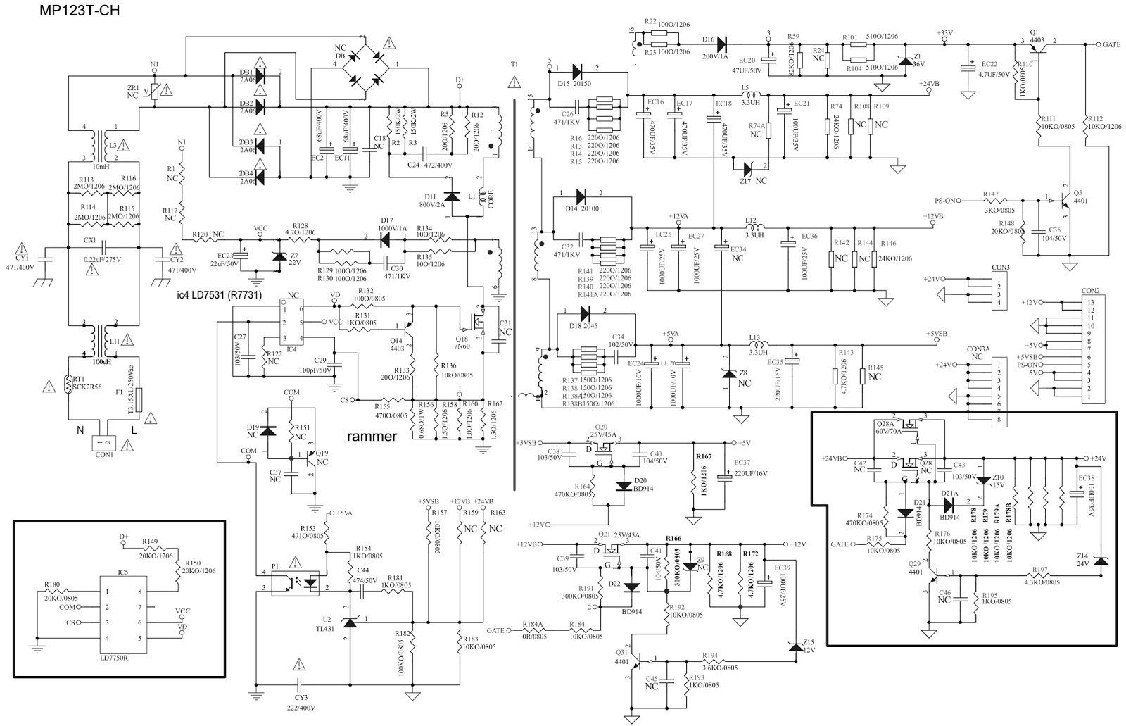
Visit the previous post here to see the SMPS schematic
Click on the schematics to magnify