SERVICE MODE - MEMORY REPLACEMENT - DEFAULT DATA VALUES - SCHEMATIC DIAGRAM - Toshiba 14N21E2
SERVICE MODE LIST
This unit provided with the following SERVICE MODES so you can
repair, examine and adjust easily.
To enter the Service Mode, press both set key and remote control key for more
than 2 seconds.
CONFIRMATION OF HOURS USED
POWER ON total hours can be checked on the screen. Total hours are
displayed in 16 system of notation. NOTE: If you set a factory initialization,
the total hours is reset to "0".
Set the VOLUME to minimum.
Press both VOL. DOWN button on the set and Channel
button (6) on the remote control
for more than 2 seconds.
After the confirmation of using hours, turn off the power.
WHEN REPLACING EEPROM (MEMORY) IC
If a service repair is undertaken where it has been required to
change the MEMORY IC, the following steps should be taken to
Ensure correct data settings while making reference to TABLE. [No need setting for after INI 16 due to
the adjustment value.]
Enter DATA SET mode by setting VOLUME to minimum.
Press both VOL. DOWN button on the set and Channel button (6) on the remote control for more
than 2 seconds
ADDRESS is now selected and should "blink". Using the
VOL. +/- button on the remote, step through the ADDRESS until required ADDRESS to be changed is reached.
Press OK to select DATA. When DATA is selected, it will "blink".
Again, step through the DATA using VOL. +/- button until required DATA value
has been selected.
Pressing OK will take you back to ADDRESS for further selection if necessary.
Repeat steps 3 to 6 until all data has been checked.
When satisfied correct DATA has been entered, turn POWER off (return to STANDBY
MODE) to finish DATA input.
After the data input, set to the
initializing of shipping.
Turn POWER on.
Press both VOL. DOWN button on the set and Channel button (1) on the remote control for more
than 2 seconds.
After the finishing of the initializing of shipping, the unit will turn off
automatically.
The unit will now have the correct DATA for the new MEMORY IC.
Confirmation of Fixed Value
Check if the fixed values of the each adjustment items are set
correctly.
To check for the fixed values of the RF (60Hz), indicate the
adjustment mode screen while input the 60Hz video signal.
SMPS SECTION CIRCUIT
DEFLECTION & CRT BOARD CIRCUIT
CHROMA-VIF SECTION CIRCUIT
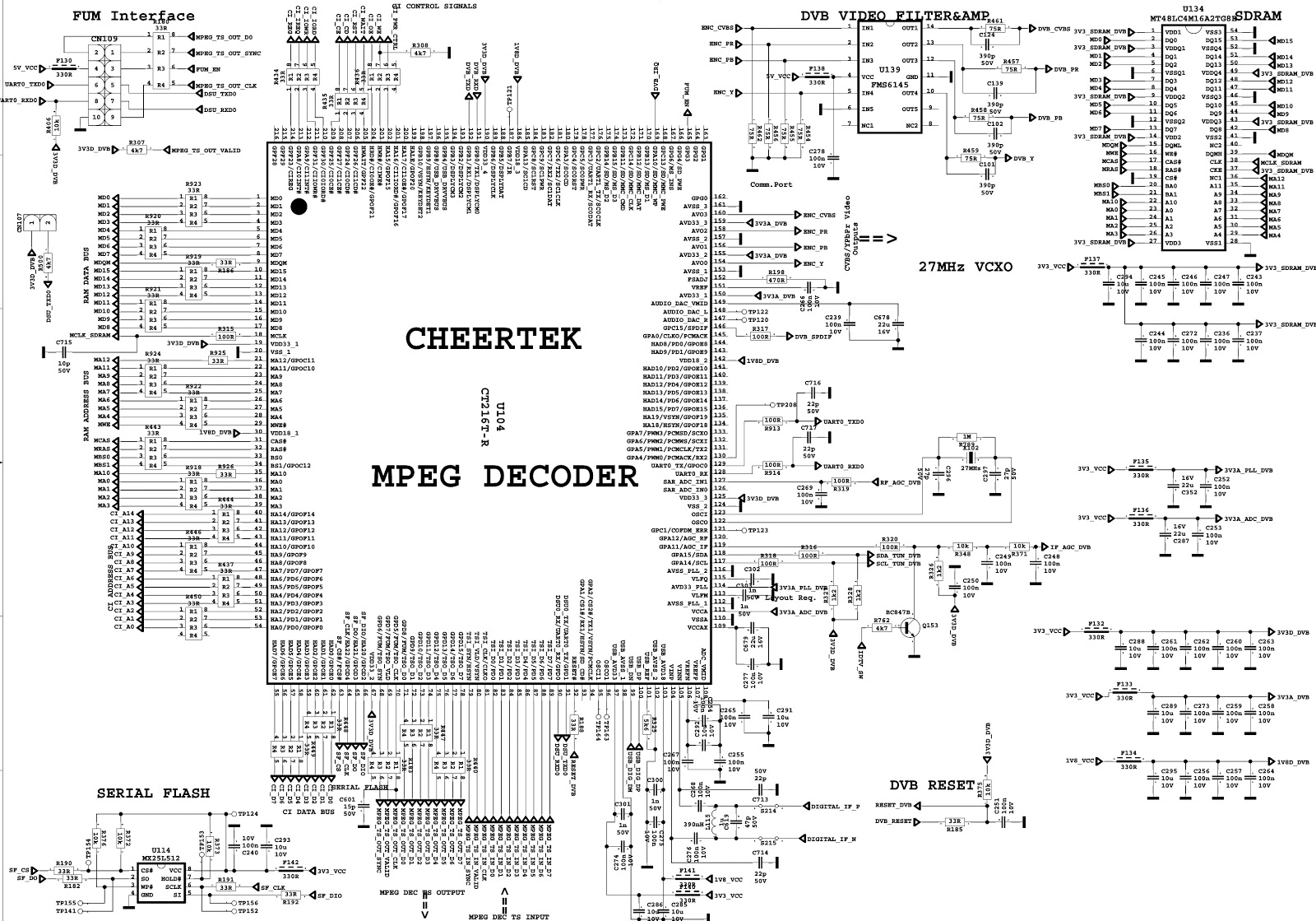
SYSTEM CONTROL SECTION CIRCUIT
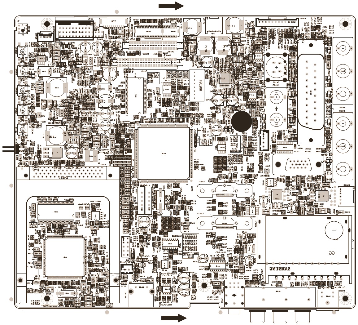
CLICK ON THE PICTURES TO ZOOM IN