Sanyo LCE 24R45FHD - software update, white balance adjustment, service mode, unit adjustment, SMPS and audio output schematic, Universal remote control set-up codes and more...
Working
principle analysis
RF
signal from antenna is sent into TUNER301 to be processed by HF-amplified and
frequency mixing, then IF signal is outputted to SWF Z301 to be IF filtered to
get ideal IF characteristics, then the signal is sent to main chip N101(RTD2674S)-27#,28#
to be amplified by inline IF amplifier and synchronous demodulated to get CVBS.
Video and audio signal from AV and YPbPr are sent to main chip N101 directly; video
and audio signal from VGA and HDMI1, HDMI2 are also sent to main chip N101
directly.
Main chip N101(RTD2674S) is a special large scale IC with full functions, such as
HDMI interface process, video decoding, video switch selection, A/D and D/A
transformation, interleaved/successive scans, mode transformation, OSD and
low-voltage difference output process, etc.; furthermore, it also has functions
of audio selection and process, MCU, etc.; external video signal is processed
by main chip N101(RTD2674S), then 4 pairs of difference signals and one pair of
clock signals are outputted to LCD to display; external audio signal processed
by main chip N101(RTD2674S) is sent to sound amplifier N501( TAS5711) to be amplified
and then to speakers.
Unit
adjustment
According to wiring diagram ‘9242KC4201JL’ , ‘9222KC4201JL’,
‘9219KC7201JL’ , ‘9224KC7001J’ , "9224KC6801JL" or ‘9232KC7001JL’,
connect main board, power board, key board and IR board correctly, switch on
power supply, check if display is normal?
Instruction of factory menu
a) First press key ‘Program source’, then press
number keys “2,5,8,0” in turn to enter initial factory menu;
b) Press keys “Up ” and
“Dn ” to move cursor to each adjustment page of initial factory menu, then
press “Right ” to enter into its adjustment menu;
c) Press keys “Up ” and
“Dn ” to move cursor upwards or downwards within any adjustment page;
d) Press keys “Left ”
and “Right ” to adjust any item when cursor is moved onto it;
e) Press key “Menu” to
exit to initial menu from any adjustment page;
f) Press key “Exit” to
exit from factory menu in any case;
g) Set item “Aging
Mode” as “On” to enter into factory aging mode.
White balance adjustment
Before adjustment
The unit should be working for above 30 minutes to be in stabler state; Use
apparatus CA210 to adjust white balance;
For model of which dimension is bigger than 26”, only 9300K color temperature
(that is “normal”) is needed adjustment, To guarantee BBY test requirements to
be met when color temperature are 12000K and 6500K, make sure that chromaticity
coordinates of bright scale are (X=285±5, Y=293±8) and chromaticity coordinates
of dark scale are (X=285±8, Y=293±12);
For model of which dimension is 26” or smaller than 26”, only 8000K color
temperature (that is “normal”) is needed adjustment, To guarantee test
requirements to be met when color temperature are 9300K and 6500K, make sure
that chromaticity coordinates of bright scale are X=295±5, Y=305±8) and
chromaticity coordinates of dark scale are (X=295±8, Y=305±12);
White balance adjustment of HDMI channel
Input 16-grey-scale signal with format of 800×600/60 Hz (VG848: Timing is 854, PAT is 921), enter into submenu “color
temperature adjustment” of factory menu;
For model of which dimension is bigger than 26”, select “normal” color
temperature (that is 9300K), fix item “G Offset”, adjust items “R Offset, B
Offset” to set chromaticity coordinates of the 3rd scale as ( 285±8, 293±12) and guarantee luminance within the range of 3 nit
to 5 nit; fix item “G GAIN”, adjust items “R GAIN, B GAIN” to set chromaticity
coordinates of the reverse 3rd scale as ( 285±8, 293±12) ; adjust items “R Offset, B Offset” and “R
GAIN, B GAIN” repeatedly until chromaticity coordinates of both scales are all ( 285, 293) ;
For model of which dimension is 26” and small than 26”, select “normal” color
temperature (that is 8000K), fix item “G Offset”, adjust items “R Offset, B
Offset” to set chromaticity coordinates of the 3rd scale as ( 295±8, 305±12) and guarantee luminance within the range of 3
nit to 5 nit; fix item “G GAIN”, adjust items “R GAIN, B GAIN” to set
chromaticity coordinates of the reverse 3rd scale as ( 295±5, 305±8) ; adjust items “R Offset, B Offset” and “R
GAIN, B GAIN” repeatedly until chromaticity coordinates of both scales are all ( 295, 305) ;
Set item “ALL COLOR” as “ON” after completing adjustment 4.2.3 White balance
adjustment of YPbPr channel ADC calibration of SD mode: Input color-bar signal
with format of 480i/60 Hz (VG848: Timing is 968, PAT is 918), enter into submenu “ADC
adjustment” of factory menu and select item “AUTO COLOR”, system will begin
calibration automatically, please note whether picture and data are abnormal
clearly or not (main abnormal data phenomena are that several data are very
different from the other or about 1000 more than the other); it is failed to
calibrate ADC if data are abnormal clearly, so it is necessary to do the
calibration again;
ADC calibration of HD mode: Input color-bar signal with format of 1080i/60 Hz
(VG848: Timing is 972, PAT is 918), enter
into submenu “ADC adjustment” of factory menu and select item “AUTO COLOR”,
system will begin calibration automatically, please note whether picture and
data are abnormal clearly or not (main abnormal data phenomena are that several
data are very different from the other or about 1000 more than the other); it
is failed to calibrate ADC if data are abnormal clearly, so it is necessary to
do the calibration again;
White balance adjustment: Input 16-grey-scale signal with format of
1080i/60 Hz (VG848: Timing is 972, PAT is 921), check if white balance is normal,
if not, enter into submenu “color temperature adjustment” of factory menu, set
item “ALL COLOR” as “OFF”, please refer to step 4.2.2 to adjust white balance
for model of which dimension is 26” , bigger than 26” or smaller than 26”
respectively;
Note: Item “ALL COLOR” must not be altered as “ON” again once set as “OFF”.
White balance adjustment of VGA channel
Auto-calibration: Input square signal with format of 800×600/60 Hz (VG848:
Timing is 854, PAT is CROSS) to do
calibration automatically in order to make window filled with picture;
ADC calibration: Input monochrome signal with format of 800×600/60 Hz (VG848:
Timing is 854, PAT is 948), enter
into submenu “ADC adjustment” of factory menu and select item “AUTO COLOR”,
system will begin calibration automatically, please note whether picture and
data are abnormal clearly or not (main abnormal data phenomena are that several
data are very different from the other or about 1000 more than the other); it
is failed to calibrate ADC if data are abnormal clearly, so it is necessary to
do the calibration again;
White balance adjustment: Input 16-grey-scale signal with format of 800×600/60
Hz (VG848: Timing is 854, PAT is 921), check
if white balance is normal, if not, enter into submenu “color temperature
adjustment” of factory menu, set item “ALL COLOR” as “OFF”, please refer to
above step.
to adjust white balance for model of which dimension is 26” , bigger than 26”
or smaller than 26” respectively;
Note: Item “ALL COLOR” must not be altered as “ON” again once set as “OFF”.
White balance adjustment of AV channel
Input 16-grey-scale signal with format of PAL (VG848: Timing is 969, PAT is 921), check if white balance is normal,
if not, enter into submenu “color temperature adjustment” of factory menu, set
item “ALL COLOR” as “OFF”, please refer to step 4.2.2 to adjust white balance
for model of which dimension is 26” , bigger than 26” or smaller than 26” respectively;
Note: Item “ALL COLOR” must not be altered as “ON” again once set as “OFF”.
4.2.6 Auto-white balance adjustment
ADC pre-calibration
Enter into factory menu, set “Program source” as “YPbPr”, input color-bar
signal with format of 480i/60 Hz (VG848: Timing is 968, PAT is 918), enter into submenu “ADC
adjustment” of factory menu and select item “AUTO COLOR”, system will begin
calibration automatically; input color-bar signal with format of 1080i/60 Hz
(VG848: Timing is 972, PAT is 918), enter
into submenu “ADC adjustment” of factory menu and select item “AUTO COLOR”,
system will begin calibration automatically,
Press key “Menu” to be back to upper menu, set “Program source” as VGA”, input
monochrome signal with format of 800×600/60 Hz (VG848: Timing is 854, PAT is 948), enter into submenu “ADC
adjustment” of factory menu and select item “AUTO COLOR”, system will begin
calibration automatically,
White balance adjustment (models except LC-19KC72, LC-22KC72)
TV set should be working for above 30 minutes to be in stabler state before
white balance adjustment; connect CA210 to USB port of PC with data line;
connect VG848 and TV to COM port of PC or virtual COM port respectively
(default connection: VG848 to COM5,TV to COM1, the connection can be altered
and saved in administrator window with password “xoceco” if necessary); output
signal of VG848 must be sent to AV1, YPbPr, VGA and HDMI1 channels of TV;
Open program file “White_Balance.exe”, load configure file “AdjustConfig.txt”,
then connect CA210, VG848 and TV respectively according to the instruction on
interface.
Note: set probe to “0-CAL” before connecting CA210, press “connect CA210”, set
probe back to “MEAS” after prompt “CA-210 connection and calibration are normal
!” appears on the left-down side;
BBY channel is used by CA210 for BBY models, for other models, channels except
BBY are used by CA210; please enter into administer window with password
“xoceco” to alter and save apparatus setting if it is different;
At last, press “Begin auto-white-balance-adjustment”, auto-adjustment will be
completed until prompt “Adjustment is successful” appears.
White balance adjustment (models except LC-19KC72, LC-22KC72)
TV set should be working for above 30 minutes to be in stabler state before
white balance adjustment; connect CA210 to USB port of PC with data line;
connect VG848 and TV to COM port of PC or virtual COM port respectively
(default connection: VG848 to COM5,TV to COM1, the connection can be altered
and saved in administrator window with password “xoceco” if necessary); output
signal of VG848 must be sent to AV1, YPbPr, VGA and HDMI1 channels of TV;
Note: Channel shared by AV/YPBPR must be adjusted respectively.
Open program file “White_Balance.exe”, if current working progress includes AV
channel, enter into channel setting of administer window to make sure no
YPBPR576i@60 but AV is chosen, or load configure file “AdjustConfigAV.txt”; if
current working progress includes YPBPR channel, enter into channel setting of
administer window to make sure no AV but YPBPR576i@60 is chosen, or load configure
file “AdjustConfigYPBPR.txt.txt”; then connect CA210, VG848 and TV respectively
according to the instruction on interface.
Note: set probe to “0-CAL” before connecting CA210, press “connect CA210”, set
probe back to “MEAS” after prompt “CA-210 connection and calibration are normal
!” appears on the left-down side; BBY channel is used by CA210 for BBY models,
for other models, channels except BBY are used by CA210; please enter into administer
window with password “xoceco” to alter and save apparatus setting if it is
different;
At last, press “Begin auto-white-balance-adjustment”, auto-adjustment will be
completed until prompt “Adjustment is successful” appears.

Performance
check
TV port
Connect RF port to central signal source, first enter into channel menu, then
auto search programs, check if there is any omitted program ,output of speakers
and picture are normal
AV/S-Video port
Input AV/S signal to corresponding terminal respectively, check if picture and
sound are normal.
YPbPr/YCbCr port
Input YUV signal from signal general VG848 with YUV format listed as Table 8,
check if picture and sound are normal.
VGA port
Input VGA signal from signal general VG848 with VGA format listed as Table 9,
check if picture and sound are normal, if not, enter into menu to do
auto-calibration.
HDMI port
Input HDMIsignal from signal general VG849 with VGA format listed as Table
8&9 , check if picture and sound are normal
USB port
Inset U disk, check if JPEG picture and MP3 music are displayed normally
AV OUT port
Check if picture and sound of AV OUT are normal
Check other functions
Check if time-on/off, sleeping time, picture/sound mode, OSD, still
picture/mute and microcrystalline-magical-picture, etc., are normal.
User menu setting before leaving factory
Enter into factory menu, select item ‘Reset’, TV set will be preset
automatically before leaving factory. Be sure to do the step after completing
adjustments in factory.
Instruction for software burning in factory as Table 10
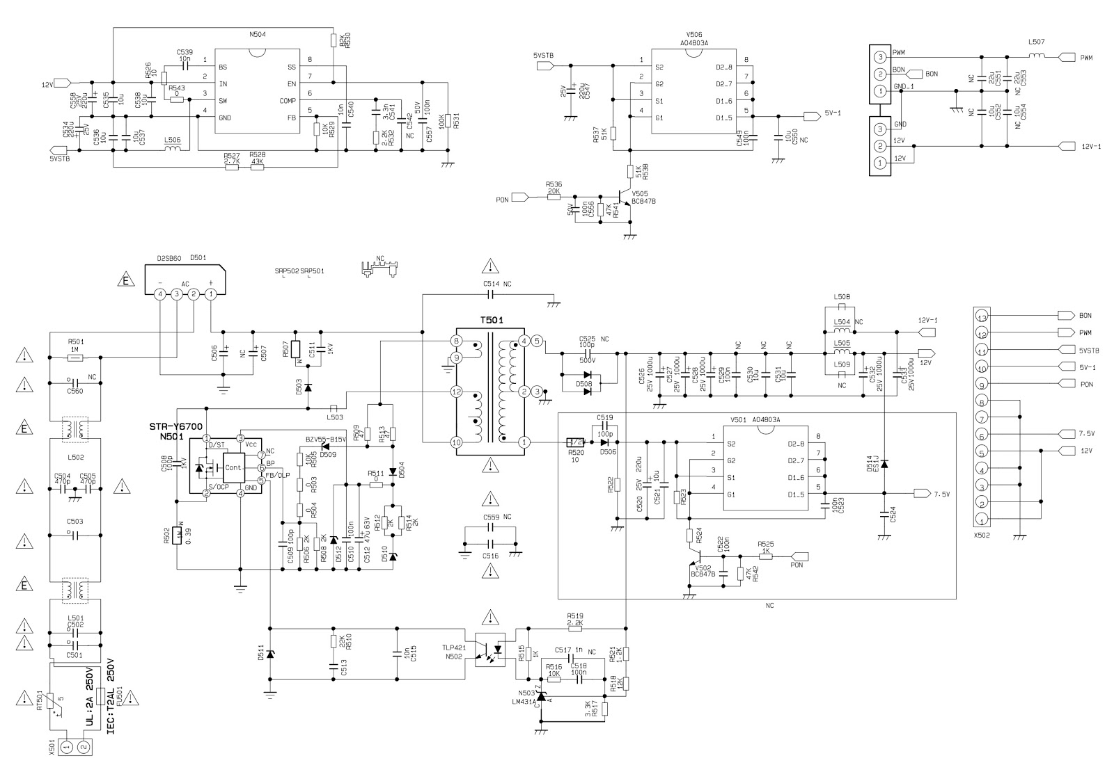
SMPS schematic
Audio output schematic
Click on the pictures to magnify
Software
upgrade
Instruction of software upgrade for KC# model:
1. Save upgrade file “flash.img” into the root directory of a U disk;
2. Insert the U disk into USB port of TV set, press key “power” until TV set is
in “standby” state, then power on TV set again;
3. Press key “program source” until menu “program source” display, then press
keys “2”, “5”, “8”, “0” by turn to enter into factory menu.
4.
Press keys of remote control “▲”,”▼” to select item “ISP”, press key “enter” to
begin updating progress, a prompt “Updating, Pls, Waiting…” is displaying, wait
for a while until menu display (TV set is unable to accept other operation
now).
5.
TV set will auto-reset after completing update, according to step1 and step 2,
enter into factory menu again to confirm updating completion by checking the
time of update file.
Universal remote
control set-up code list for Sanyo brand TVs
0018 0020 0041 0049 0050 0065 0101
0102 0107 0131 0139 0152 0161 0166 0177 0181 0195 0198 0209 0215 0314 0320 0379
0391 0408 0421 0634 0660 0667