TDA9341
– AT24C08 - CD4052 – AN7522 – TDA2003 – [LOT
BSC25-N0832/BSC25-T1010A/BSC24-01N4014K] – Transistorized SMPS
FBT variations: FOR 29”
BSC26-01-N4010F BSC26-N2143
BSC26-01N4010E BSC26-N2148
BSC26-01N4004F BSC26-01N
REPLACEMENT OF MEMORY IC
This TV circuit uses memory IC. In the memory IC are memorized data for correctly operating the video and deflection circuits.
When replacing memory IC, be sure to use IC written with the initial value of data.
PROCEDURE FOR REPLACING MEMORY IC
(1) Power off
Switch the power off and unplug the power cord from AC outlet.
(2) Replace IC
Be sure to use memory IC written with the initial data values.
(3) Power On
Plug the power cord into the AC outlet and switch the power On.
(4) Check and set system default value:
1) Press “MENU” key followed by digits '6''4''8' and '3'. Then Press “TEST” key on the Remote control unit for factory used.
2) The red “M”or”factory” will be displayed on the screen, repeat this and it will changed as follow:
normal-M(factory)-BUS open-normal..
3) Press digital key, (Mkey) and corresponding on-screen display will be appeared.
4) Check the setting value of the SYSTEM default value of Table below. If the value is different, select items by [CH+]/[CH-] keys and set value by VOL+]/[VOL-] keys.
5) Press “STANDBY” key again and return to the normal screen.
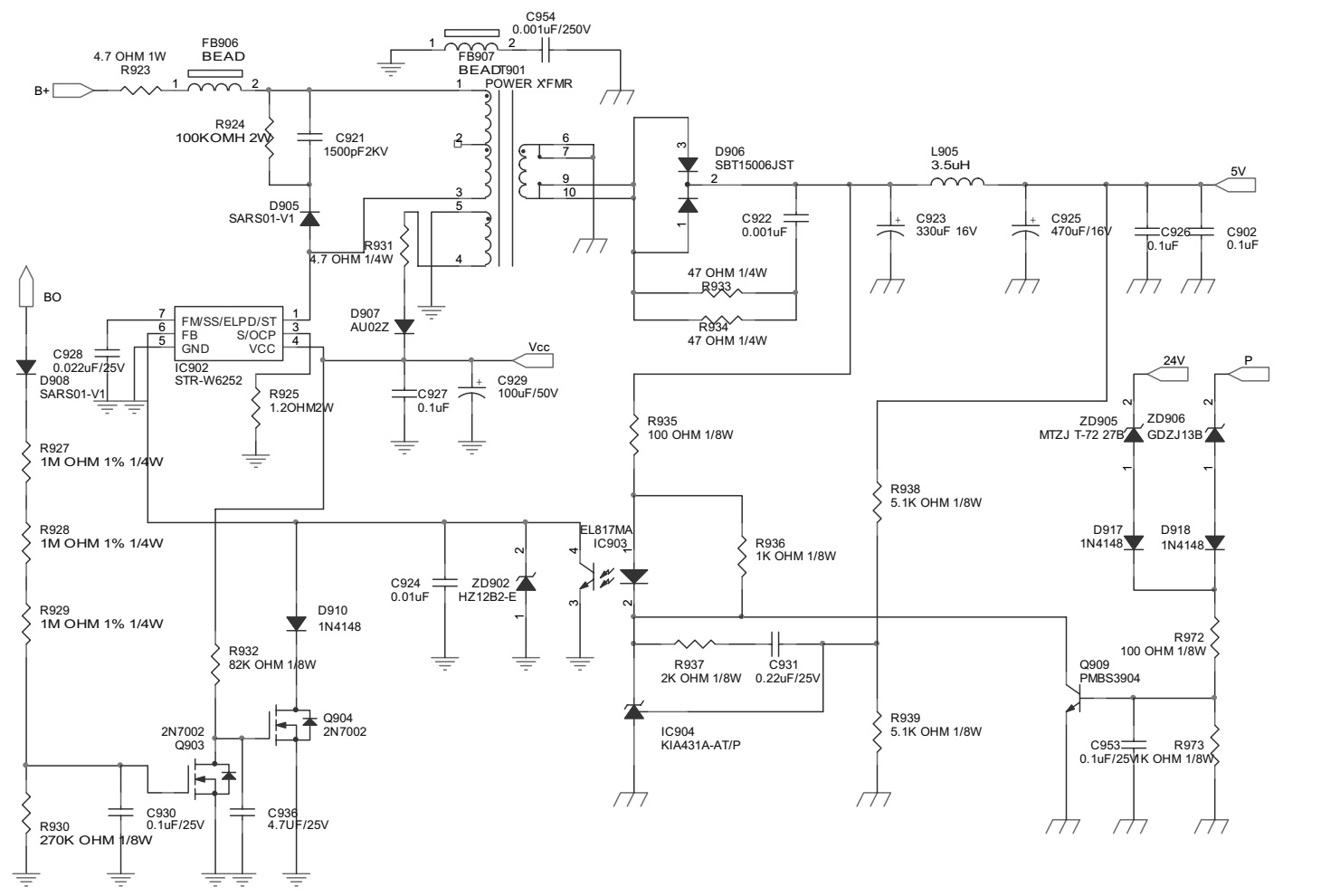
Circuit diagram and PWB
BUS CONTROL ADJUSTMENT
TDA9351/9353: to enter BUS control mode, Press “MENU” key followed by digits '6''4''8' and '3'. Then press digit Press “0” to “9“ key, (Mkey) and corresponding on-screen display will be appeared.
TDA8370: to enter BUS control mode, Press “MENU” key followed by digits '6''4''8' and '3'. then Press “TEST” key on the Remote control unit twice for factory used(or press digits '6''4''8' and '3' twice.) and then press digit Press “0” to “9“ key, (Mkey) and corresponding on-screen display will be appeared.
On TV screen “TEST” will be indicated, this means entered bus control mode.
And press following key, each function will be available.