Burning on the circuit board EWM1000
In case of burning on the main circuit board, check that the problem is not
caused by another electrical component (short-circuits, poor insulation, water
leakage).
Refer to the figures below in order to identify the component that might have
caused the burning according to the position of the burned area.
The circuit board shown below is the version with the greatest number of
components: other boards may not feature all these components (relay K4 and
buzzer).
1. NTC washing temperature sensor
2. Drain pump
3. Power supply
4. Motor
5. Heating element
6. Door safety interlock
7. Water fill solenoids
8. Tachymetric generator (motor)
9. Drum positioning system (top-loaders)
Pushbutton – led side (horizontal
buttons) & Pushbutton – led side (vertical buttons)
Connectors on circuit board EWM1000
1. ---
2. Drain pump
3. Power supply
4. Motor
5. Heating element
6. Door safety interlock
7. Water fill solenoids
8. Tachymetric generator (motor)
9. Drum positioning system (top-loaders)
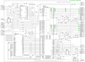
Elementary diagram
With instantaneous door locking device
and With PTC door locking device & With PTC door locking device
KEY TO CIRCUIT DIAGRAM
1. Circuit board
2. Suppressor
3. Main switch (on programme selector)
4. Door safety interlock
5. 1st level pressure switch
6. Anti-boiling pressure switch
7. Anti-overflow pressure switch (certain models only)
8. Heating element
9. Stator (motor)
10. Overload circuit-breaker (motor)
11. Tachymetric generator (motor)
12. Rotor (motor)
13. Drain pump
14. Pre-wash solenoid valve
15. Washing solenoid valve
16. “Door closed” lamp (certain models only)
17. Drum positioning system (DSP) (top-loaders – certain models only)
DOOR_TY Triac for door safety interlock
DRAIN_TY Triac for drain pump
K1 Heating element relay
K2 Motor relay: clockwise rotation
K3 Motor relay: anti-clockwise rotation
K4 Motor relay: half-range power (certain models only)
MOTOR_TY Motor triac
ON/OFF Main switch (programme selector)
PWELW_TY Triac for pre-wash solenoid valve
Serial interface Asynchronous serial interface
WELV_TY Triac for washing solenoid valve


