Used with - Haier P32R1, Haier L32F1, Haier LK32K1, Haier L32R3and Vizio VOJ320F1A
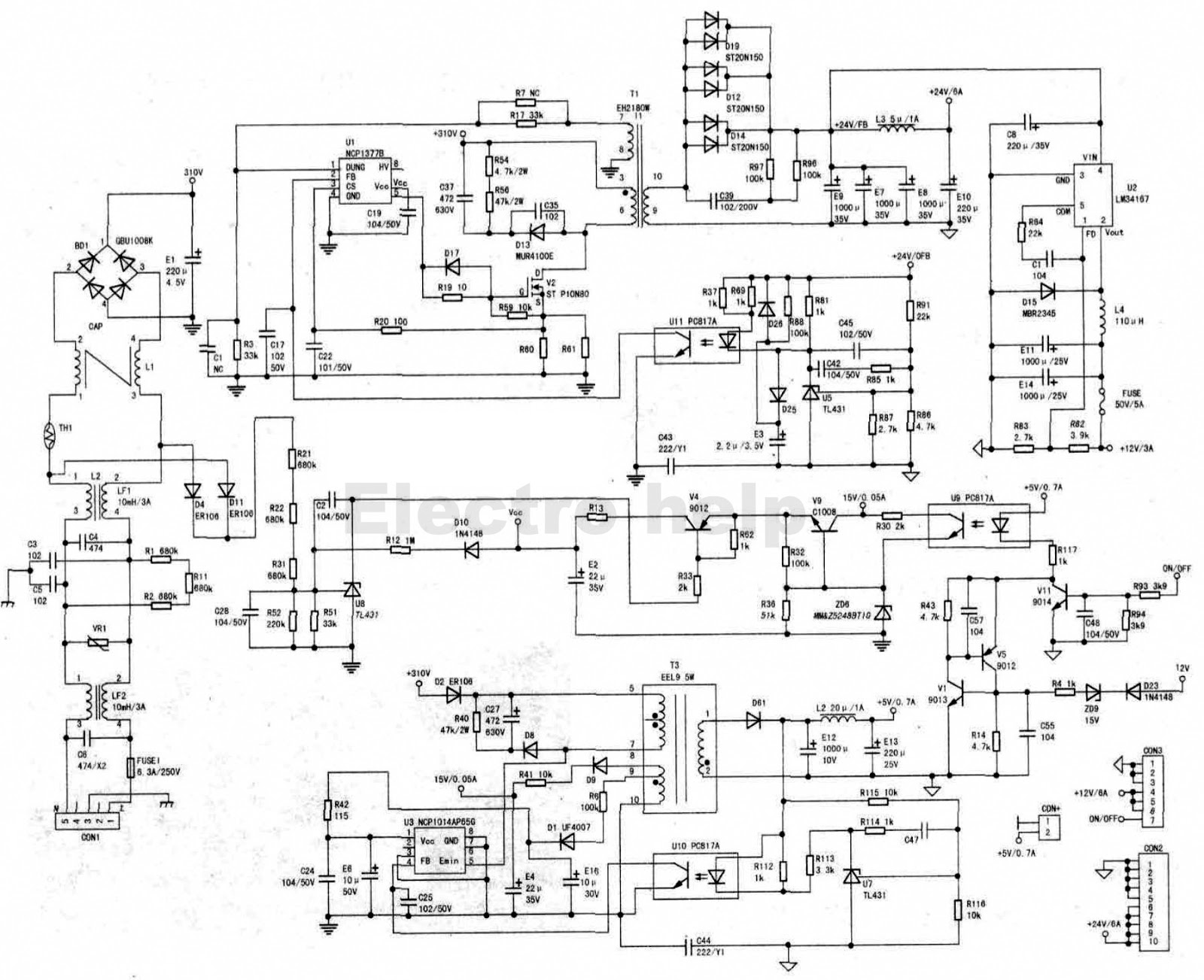
Haier L32Fl LCD TV power supply voltage is + 5V, +12 V and +24 V three groups, of which 5V for the standby power, to the motherboard standby circuit power supply, 12V to the motherboard power supply, 24V to the back-light board power supply.
Standby circuit start process
Power board connected to the mains, 220V by C6, LF2, VR1,
C3, C5, C4, LF1, Ll filter, and then by BD1 rectifier, Cl filter, get +103 V
DC, divided into two by Tl and T3 transformer primary added to the V2
"D" pole, standby power supply chip U3 (NCP1014AP65G) (5) feet.
Leaving aside the main power circuit for the time being, say U3 Standby power
chip, U3 (5) feet after the power, the chip built-in boot circuit first to E6
charge, when the E6 voltage rises to About 7.5V. U3 internal oscillation
circuit began to oscillate into the working state, U3 work after the T3
transformer primary auxiliary Winding generation of 12V, 15V two groups of DC voltage. 12V
for the U3 work to provide secondary power supply, to maintain oscillation; 15V
then three poles Tube V9 (C1008) c pole. V9 controlled by the on / off control
circuit to achieve the main power supply Ul power supply control. T3
transformer secondary Produce + 5V / 0.7A voltage to the motherboard control
circuit (key processing, remote control signal processing, on / off processing
circuit J for Electricity. D8, C27, R40 for the spike absorption circuit,
inhibit the switch in the off when the peak pulse generated damage U3 Switch tube.
5V standby voltage regulator
+ 5V voltage by R115, R116 divided to U7 (TL431) (1) pin reference voltage input, through the internal circuit Control voltage output. U7 is characterized by (1) pin voltage rise, (3) pin voltage drop. U1 (4) pin voltage is controlled by Ul0, Adjust the chip built-in PWM generator duty cycle, forcing the secondary output voltage stability.
Main power circuit start process
When the motherboard receives the power on signal, the motherboard output on / off control voltage (+5 V) by CON3 connector (7) Feet added to the V11 (9014) b pole, so that the c-pole potential pulled low, U9 (PC817) optocoupler power conduction, 15V by R30, U9 secondary To V9 (C1008) b pole, so that V9 conduction. V9 e output + 12V voltage by V4, R13 added to the Ul (6) feet. U8 (TL431), D4, Dll (ER106), R21, R22, R31, R52, R51 and other components of the mains voltage detection circuit, under normal circumstances, V4 Was turned on. AC 220V voltage is too low, U8 trigger pin (1) pin voltage drop, U8 cut off so that V4 to stop working, No vCC for Ul work, the machine was standby state. Ul (NCP1377B) main power chip (6) feet get 12V operating voltage , The internal oscillator starts to work, the (5) pin output PWM signal added to the control of V2, so that V2 work in high-frequency open Off state. In the Tl to produce a change in the pulse voltage, Tl primary pulse voltage generated in the T1 secondary induced voltage by D12, D14, D19 (ST20N150) fast recovery diode rectifier, the E7, E8, E9, C8, El0 filter to get +24 V / 6A power Pressure. The U2 (LM34167) circuit is a DC-DC converter that converts the + 24V voltage to + 12V / 3A, E14 filter output.
Click on the pictures to zoom in

Main power circuit regulator process
R91, R86, R87 components of the partial pressure sampling
circuit, when the +24 V voltage increases, the partial pressure sent to U5
(TL431) (1) feet, U5 (3) pin voltage becomes low, U11 (PC817) optocoupler
conduction, the Ul (NCP1377B) main power chip (2) the pin potential is pulled
low, the power chip output PWM duty cycle decreases. V2 (MOS) tube conduction
time becomes shorter, so that the transformer The secondary voltage is reduced
to complete the regulator process. +2 4V
voltage regulator when the voltage regulator circuit with the above process is
the opposite process.
Main power over-current detection circuit
When a cause causes the current in the V2 MOS tube to
increase. R60, R61 resistance on the pressure drop also increased The voltage
is supplied to the Ul (3) pin current detection via R20 when the (3) pin
voltage rises to the chip threshold voltage. Ul main power chip stop Vibration,
thus avoiding V2 over-current damage.
Main power over-voltage detection circuit
When some cause caused +103 V voltage rise, Tl transformer
(7) feet induced voltage is also increased, R3 The voltage will rise, when the
voltage of R3 to the chip (1) internal set value, the over-voltage protection
circuit action, Ul stop vibration.
How to determine if the fault is on the power board.
The power board can be removed from the machine, so repair
more convenient. Place the power supply board face up and place it on an
insulated desk. Be sure to pay attention to insulation. Use a wire to shorten the + 5v with the CON3
connector ⑦ pin (ON / OFF) to start the power supply.
After receiving the dummy load, use a multimeter to detect +
5V (CON4 connector (1) a (2) feet), + 12V (CON3 (2) a (5) feet), +24 V (CON2
connector (3) a (8) feet) voltage is normal, such as the three groups of
voltage is not normal, Can determine the fault in the power board, otherwise
the other circuit failure.
(1) false load general power board secondary output socket are marked with the current value of each group of voltage, according to this current
Value to calculate the load resistance value easily. Such as: 12V / 3A-4Ω / 36W. For easy maintenance, with lOkΩ resistor with oneOnly LED series connected to the dummy load, can be intuitive to indicate the power of each group of voltage work.
(2) Note that the best power with a switch with the socket, first connect the power cord, and then press the switch, do not leave the first hand.
Such as lOs after the elements do not smoke, burst and other abnormalities can be detected.
Power board power, El ends are still about 30V high pressure, please use PTC before the maintenance (positive temperature coefficient Thermistor J is its discharge.
(3) "three noes" maintenance process "three no" fault most of the power board failure, this time do not blindly power detection, Should first "look", see the power board rectifier bridge, +103 V filter capacitor, MOS tube, switching power supply chip and other large power components Whether the surface is black, charred, burst and other anomalies, so that you can quickly find the fault area, reduce the fault detection range, But also to prevent blind power caused by the failure to expand again, causing security risks. If no anomalies are found, they can be energized and measured + 5V (CON4 connector (1) feet) voltage is normal, such as voltage is not normal or no voltage, then the standby power supply circuit work abnormal. At this time can be measured in turn + 310V (El ends) voltage, standby power supply chip power supply VCC + 7.8V (E6) voltage, And determine whether ZD3, U3, T3, R6, R42, L2, etc. are faulty.

(4) +5 V voltage is not normal maintenance process + 5V voltage is low or unstable is generally sampling feedback circuit, power chip vibration And drive circuit failure. Can detect standby power supply chip VCC + 7.8V (E6) voltage, if the voltage is normal, then Can determine the fault in the sampling feedback circuit. Such as abnormal main detection of the power chip itself or power chip oscillation and drive the electricity
(5) + 5V normal, do not boot maintenance process without +12 V, +24 V voltage.
Fault range is relatively large, there are on / off circuit, the main power oscillation circuit, the main power supply sampling feedback circuit.
Maintenance should first test CON3 connector (7) feet whether the 5V boot voltage, if not, then the fault in the motherboard standby power Road, such as normal can be carried out in accordance with the following steps to repair.
It is to be noted that the power supply board is made of R21, R22, R31, R51, R52, U8, R33, V4, R13 and other components of the mains detection circuit, such as the above components are open or bad, will lead to +15 V on / off voltage cannot be smooth To the Ul (NCP1377B) main power chip (6), so that the main power supply can not start. + 12V and + 24V are no output. Such as arms Suspected of this circuit is faulty, can V4 (9012) c-e very short, such as the normal power supply to start, that failure in the circuit, such as still not See the power to start, indicating fault in other circuits
(6) no +12 V voltage output maintenance process +12 V DC-DC circuit is relatively simple, generally U2 (LM34167) Bad, overhaul can be changed, such as can not rule out the fault, you can check L4, R82, R83, R84 and other components.